Graphic LCD 84x48 - Nokia 3310
Replacement:LCD-10168. We are no longer carrying this LCD because we couldn't find an appropriate connector. This page is for reference only.
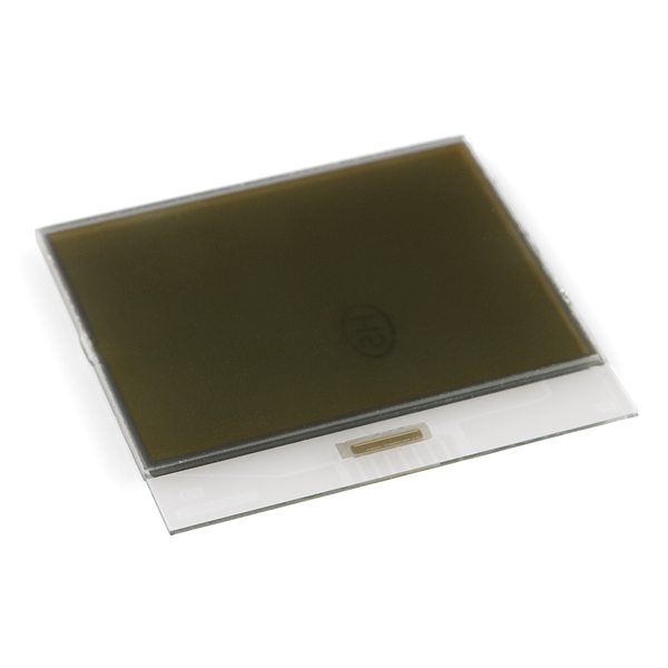
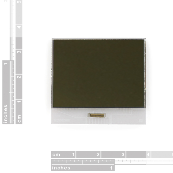
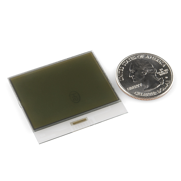
This is a small monochrome LCD 84x48 pixel display that was used in the immensely popular Nokia 3310 phone. This is a very low power display (less than 1mA) but has no backlight. Great for low power remote node applications.
Search google for Nokia 3310 LCD and you will find lots of documents and resources including pin outs.
This is just for the bare LCD. At this moment we do not have a mating elastomeric connector yet. We are attempting to source one though.
Replaces:LCD-08629
Comments
Looking for answers to technical questions?
We welcome your comments and suggestions below. However, if you are looking for solutions to technical questions please see our Technical Assistance page.
Customer Reviews
No reviews yet.


I came across this :
http://www.dealextreme.com/details.dx/sku.37786
No idea what the size is..
According to the DX website linked, "Dimensions: 0.31 in x 0.04 in x 0.04 in (0.8 cm x 0.1 cm x 0.1 cm)." Looking at that with my calipers, it seems like it would be perhaps a tad too short.
It might be a possibility to glue two of them together and then trim again.
Nice find. We will have one soon so you can see what is meant to mate with it. That one may or may not work.
Any updates on sourcing the connector and designing the breakout?
Nice Find!
Even if it's too big, we can always trim it. But how would we connect to the connector? bare pcb pads? wires glued on with wire glue?
--MTG
I'd use gold plated traces on a pcb.
The next hurdle is to make some kind o way to mount the fragile glass unit on a PCB. Maybe combined with some kind of backlighting or sidelighting.
Any idea's for a laser cut transparent holder ?
Double sided foam tape and about 4 SMD LEDs might do the job. (Looks like the LCD is transparent and has a built in diffuser)
--MTG
Conductive Ink?
It is a pity this display is no longer for sale. The connection method I described earlier is not that hard to do. The PCB version can be seen at the bottom of my 3310 page.
http://nerdipedia.com/tiki-index.php?page=Nokia+3310+LCD
The 5510 is 2/3 the price of the of the nokia610 131*131 colour display so I'm not sure it is great value.
I haven't gotten mine yet to try out yet, but this website claims to sell the rubber conductor for this LCD:
http://www.cellphoneshop.net/lcdrubconstr.html?CAWELAID=507293407
OMG, I would caution anyone thinking of ordering a rubber conductor strip from that link I provided earlier.
It has been several weeks with no email communications from the vendor. No product has arrived. I just called their customer support to get status. The customer support rep wouldn't tell me if it had been shipped or not, just offered to refund or re-ship. After choosing re-ship, the lady wanted me to repeat and spell out my shipping address at the top of my lungs about 10 times before she could hear or understand. I think she was probably in India. After the nth time trying to "spell out" the number '9' for her, I just wanted a refund, but she wouldn't let me choose that option now.
edit 01/15/2011
Today my rubber conductor strips have finally arrived from Hong Kong. The shipping invoice lists 1/7/2011, so I think these are a result of my phone call to the customer support rep in India, not an original shipment from my online order made back in December.
I tried one of them out with my sparkfun LCD. It works! My firmware code will need some tweaking to support the quirks of this LCD chip as others have mentioned, but so far it is (faintly) displaying some legible text.
Here is a PicBasic Pro example for the 3310. http://www.picbasic.co.uk/forum/content.php?r=174-Using-Nokia-3310-LCD
I've been looking through several drivers people have posted for these LCDs, and they seem to have quite a few "magic constants" -- notably temperature coefficient, VOP, and VBias (maybe more; those are just the ones off the top of my head). Is there a documented source for these numbers, or have they just been discovered through trial and error?
I just found a couple of companies that manufacturer the elasomer strips, SparkFun may want to try to contact them and see if they can get a supply in...
http://www.zaxisconnector.com/
http://www.fujipoly.com/products/genProductLine.asp?ProductLine=Zebra
I just found a couple of companies that manufacturer the elasomer strips, SparkFun may want to try to contact them and see if they can get a supply in...
http://www.zaxisconnector.com/
http://www.fujipoly.com/products/genProductLine.asp?ProductLine=Zebra
MikeGrusin: It looks well-bonded, I'll run some experiments and see.
The partial silver backing on mine was a film which peeled off quite easily and cleanly.
DirectDigitalLabs: Thank you for confirming my findings!
http://forum.sparkfun.com/viewtopic.php?f=14&t=22365
Any luck on finding out what the actual controller is?
I haven't tried too hard. My guess is Sitronix ST7576
It has been a while since I read the datasheets so my memory may be faded. I think these have eeprom or something so they can be configured to drive the smaller 3310 display. I'm also guessing the "new" LCDs have directional SPI and the phone can use it to work out what display it has fitted.
eddiem: I'm getting dejavu again.
My display does not seem to have a PCD8544 controller as shown in the examples shown above.
I'm seeing the same problem as shown here.
http://www.8052.com/forum/read/170861
http://www.edaboard.com/ftopic324477.html
The display work but hides the first three rows of pixels on row-0 and it has more than the six byte rows the PCD8544 has - 3 pixels rows of byte row-6 are visible. Also the X address seems to wrap at 102 not 84 as expected.
Alternative controllers are mentioned in the pages above and I'll see if I can sort it out.
I've tested the work around on http://www.edaboard.com/ftopic324477.html
I works.
Add lcdCom(0x45); // New LCD Correction (Y offset +5)
to the initialization code and hide line zero.
I'm not sure if it is possible to do a negative offset. As is - the old and new displays would have a different Y origin.
Thank you for confirming my findings!
http://forum.sparkfun.com/viewtopic.php?f=14&t=22365
Any luck on finding out what the actual controller is?
I'm getting dejavu again.
My display does not seem to have a PCD8544 controller as shown in the examples shown above.
I'm seeing the same problem as shown here.
http://www.8052.com/forum/read/170861
http://www.edaboard.com/ftopic324477.html
The display work but hides the first three rows of pixels on row-0 and it has more than the six byte rows the PCD8544 has - 3 pixels rows of byte row-6 are visible. Also the X address seems to wrap at 102 not 84 as expected.
Alternative controllers are mentioned in the pages above and I'll see if I can sort it out.
RobertC.: Nice job! Hopefully we'll have a solution here soon, but yours looks to work great!
FYI,
My connector works. I've managed to initialize the display and have a crude test pattern up.
I thought I'd cooked it when a wiring error put 5V on the D/C line but it seems to have survived.
RobertC.: Nice job! Hopefully we'll have a solution here soon, but yours looks to work great!
Thanx Robert,
Any idea what and when your solution will be. I'm thinking of doing a PCB but might hold off if you've got something around the corner.
One more.
I've started a wiki page for the LCD. I've made a connector but not tested it yet.
The page is here - http://nerdipedia.com/tiki-index.php?page=Nokia+3310+LCD
Nice job! Hopefully we'll have a solution here soon, but yours looks to work great!
Take-3.
The pitch is not .05 in.
The glass is fairly thin and it turns out that if I gut a SIL connector similar to - http://www.sparkfun.com/commerce/product_info.php?products_id=8838
I get nice gold plated "Y" bits which happen to slide over the glass nicely. The contact is a bit too long so it either needs trimming or packing up. Eight of those plus conductive glue would probably work.
eddiem: more.
If the pitch is 1.27mm ie 0.05 inch there may be scope to use a stripped ribbon cable + conductive glue as the interface.
eddiem: I bought a display to see what it is like. Those on-glass traces are fairly large - compared to .5mm pitch sockets are least. I don't have it here but it looks like 1mm in the photo - maybe 1.27mm.
Maybe it would be possible to glue to it using some sort of conductive glue or paint. I haven't checked but I'm guessing the currents are fairly low. For example it might be possible to lay a strip of pins with the correct pitch along the edge - apply a small amount of conductive glue and reinforce with epoxy after it has set.
more.
If the pitch is 1.27mm ie 0.05 inch there may be scope to use a stripped ribbon cable + conductive glue as the interface.
eddiem: I bought a display to see what it is like. Those on-glass traces are fairly large - compared to .5mm pitch sockets are least. I don't have it here but it looks like 1mm in the photo - maybe 1.27mm.
Maybe it would be possible to glue to it using some sort of conductive glue or paint. I haven't checked but I'm guessing the currents are fairly low. For example it might be possible to lay a strip of pins with the correct pitch along the edge - apply a small amount of conductive glue and reinforce with epoxy after it has set.
I bought a display to see what it is like. Those on-glass traces are fairly large - compared to .5mm pitch sockets are least. I don't have it here but it looks like 1mm in the photo - maybe 1.27mm.
Maybe it would be possible to glue to it using some sort of conductive glue or paint. I haven't checked but I'm guessing the currents are fairly low. For example it might be possible to lay a strip of pins with the correct pitch along the edge - apply a small amount of conductive glue and reinforce with epoxy after it has set.
if you layered two of these together could you make a 3D display?
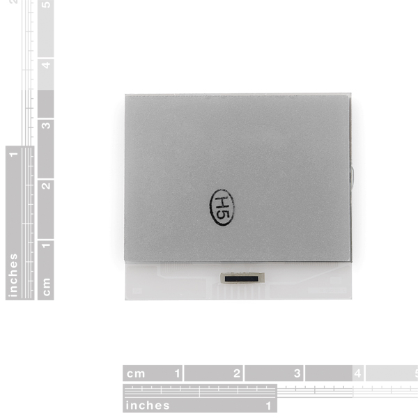
No, these have an opaque backing on them. Good idea though!
Could that be removed?
It looks well-bonded, I'll run some experiments and see.
Can the connections be soldered by hand? What's the pitch?
no, the connections on this LCD are on-glass traces. you'll need an elastomeric connector or a series of metal clips to be able to connect to it.
Sparkfun should not only get the elastomeric connectors, but also make breakout boards for these LCDs.