QCPete
Member Since: January 28, 2009
Country: United States
Profile
Bio
I started at SparkFun in September of 2007 as an assembly technician. My experience in electronics had consisted of only running sound equipment for my band and fixing the occasional broken guitar cord. After only a few days on the production floor, my skills with a soldering iron improved dramatically, and I was building beautiful little widgets. It wasn't too long before I started wondering how all these circuit boards actually worked. Whenever I had the chance, I would walk across the hallway to the engineers and ask for 5 minutes of their time. I learned words like micro controller, source code, op amp and many more. I was hooked.
My first project was an analog headphone amp. It was something I could use as a performing musician. This has since kept me busy on week nights (and most weekends) as I've grown my own business around audio products for musicians.
While perfecting my headphone amp design, I got into other DIY projects too. Before long, I was in my front lawn with my laptop and a few servos. I was hacking my sprinkler system. With some active pressure control, I was able to make my sprinkler shoot a perfect square. My neighbors thought I was a crazy :)
Little did I know that taking this position at SparkFun would open my eyes to a new favorite creative outlet, DIY Electronics. I get super stoked about a lot of things, but from the moment I felt that initial spark of interest, I knew this was something very special. I was learning tools that would allow me to truly harness my inner inventor.
In the last few years I have focused my energy at SparkFun to designing more efficient testing equipment and providing feedback to the engineers on how we can better design for manufacturing and testing. I can hardly call it a job, because I love it so much :)
Role
QC Manager
Programming Languages
Arduino, Tera Term Scripts and Batch Files.
Associations
Rock On Audio
Universities
Incline High School (Lake Tahoe), Squaw Valley Academy, Cate High School, Golden West (Huntington Beach), Cal State Long Beach, CU Boulder, Sparkfun University
Expertise
Rocking
Interests
A nice fillet and clean layouts. DSP, particularly the Sigma Studio stuff from AD. Thermal updrafts and circling in them. Remote control Airplanes - Electric in the parking lot and Slope when the winds up.
Websites
http://www.rockonaudio.com, http://www.phillewisart.com (that's my bro!)
Using cryptographic authentication, we created a super-secure remote control to open a garage!
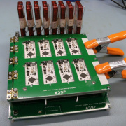
We collected over two hundred retired testbeds and turned them into art! Join us as we highlight this project and tell some of the stories behind these dusty old circuit boards.
The Longmont Innovation Center hosted a great event, focused on building community and sparking interest in STEM education!
Check out this Qwiic-based jukebox using Qwiic RFID and Qwiic MP3. Follow along with the video and hookup guide to build your own!
Guest author Kelly Small shares his experience with the evolution of test controllers from the 1980s through today.
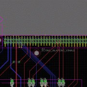
Join us for part two of our in-depth look at testbed design at SparkFun. Here, we focus on the hardware design choices for our in-house testing tool, the Flying Jalapeno.
Join us as we give some insight into the progress made in SparkFun’s testbed design over the past eleven years, and an in-depth look at our most recent production testing tool, the Flying Jalapeno.
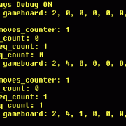
Let's take a closer look at the quasi-random sequence generator for the Simon Says Trampolines project, and how a buggy first attempt was improved!
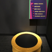
A re-creation of our Simon Says Soldering Kit using trampolines, spot lights and a ton of new sounds!
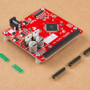
Join us for an epic journey into design for manufacturing, voltage spike suppression, stress testing, hex file analysis and more!
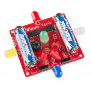
While designing our new Simon Tilts Through Hole Soldering Kit, we ultimately found that the best solution for the tilt sensor involved creating a custom plastic part. Here is the story of this project - including a couple interviews with the people that helped us along the way.
In addition to the ongoing robot competition at AVC 2013, we included some carnival-type entertainment for the attendees. We rented a dunk tank, triggered it with a swiveling mallet, and challenged people to play "Trampoline Simon Says".
Analog MEMS Microphone (VM2020) Hookup Guide
February 9, 2023
Get started with the SparkFun analog MEMS microphone breakout board! In this tutorial, we will be connecting the differential MEMS microphone to an Arduino using the WM8960 audio codec.
Audio Codec Breakout - WM8960 Hookup Guide
January 26, 2023
The SparkFun Audio Codec Breakout - WM8960 is a low power, high quality stereo codec chock full of features. In this tutorial, some of these features by using an Arduino microcontroller to configure the audio codec and pass audio to the headphone or speaker channels.
Qwiic Speaker Amp (TPA2016D2) Hookup Guide
September 29, 2022
The SparkFun Qwiic Speaker Amp includes the Texas Instruments TPA2016D2 stereo, filter-free class-D audio power amplifier. This tutorial will help you get started and configure the amplifer settings using an Arduino microcontroller.
AzureWave Thing Plus (AW-CU488) Hookup Guide
September 22, 2022
The SparkFun AzureWave Thing Plus is a Feather form-factor development board equipped with the AW-CU488. We'll highlight key features of the board and show you to get started with the development board. A few Arduino examples will be highlighted to connect to a WiFi router, calculate the Fast Fourier Transform (FFT) from an input microphone, output an analog signal to a speaker, and connect an Qwiic-enabled device.
MicroMod Single Pair Ethernet Function Board - ADIN1110 Hookup Guide
May 12, 2022
With the SparkFun MicroMod Single Pair Ethernet Function Board - ADIN1110 you can prototype and create 10BASE-T1L Ethernet connections that work in noisy environments and over exceptionally long distances of over 1 kilometer! Follow this guide to get started with this Function Board.
Getting Started with the MyoWare® 2.0 Muscle Sensor Ecosystem
April 1, 2022
The MyoWare® 2.0 Muscle Sensor, an Arduino-compatible, all-in-one electromyography (EMG) sensor from Advancer Technologies. In this tutorial, we will go over the features and related shields to connect the sensor to a muscle group.
Artemis Global Tracker Hookup Guide
December 9, 2021
The SparkFun Artemis Global Tracker combines the Artemis processor with an Iridium 9603N satellite transceiver, ZOE-M8Q GNSS transceiver, and MS8607 PHT sensor. With a clear view of the sky, this board allows you to send and receive short data messages from anywhere in the world including remote locations far beyond the reach of WiFi and GSM networks. Follow this guide to get started with the Artemis Global Tracker.
Air Velocity Sensor Breakout - FS3000 Hookup Guide
September 23, 2021
Get started with the Air Velocity Sensor Breakout - FS3000!
Digital Temperature Sensor Breakout - AS6212 (Qwiic) Hookup Guide
September 9, 2021
Get started measuring highly accurate temperatures at extremely low power with the AS6212 temperature sensor on the SparkFun Digital Temperature Sensor Breakout - AS6212 (Qwiic).
ESP32-S2 Thing Plus Hookup Guide
April 8, 2021
Looking to use the more secure ESP32-S2? Follow this hookup guide to get started.
SparkFun expLoRaBLE Hookup Guide
February 4, 2021
Check out our latest LoRaWAN development board with Bluetooth capabilities! With this guide, we'll get you passing data to The Things Network in no time.
SparkFun Qwiic 3-Axis Accelerometer (ADXL313) Hookup Guide
November 5, 2020
Let's get moving with the SparkFun Triple Axis Digital Accelerometer Breakout - ADXL313 (Qwiic), a low cost, low power, up to 13-bit resolution, 3-axis accelerometer with a 32-level FIFO stack capable of measuring up to ±4g. This hookup guide will get users started reading measurements from the ADXL313, by Analog Devices, with an Arduino microcontroller, Jetson Nano, or Raspberry Pi.
SparkFun Qwiic Shield for Teensy Hookup Guide
October 15, 2020
A short guide for assembling and using the SparkFun Qwiic Shield for Teensy and Qwiic Shield for Teensy Extended.
SparkFun ProDriver and Mini Stepper Motor Driver Hookup Guide
September 3, 2020
The SparkFun ProDriver and Mini Stepper Motor Driver boards utilize Toshiba's TC78H670FTG stepper motor driver. The ProDriver features latch pin terminals, which are easier to connect than the "Easy" Drivers. Meanwhile, the Mini Stepper Motor Driver come in smaller PCB footprint, that is pin compatible with breadboards. To get started, follow this hookup guide and you will be spinning stepper motors, in no time.
Secure DIY Garage Door Opener
January 16, 2020
Did you know that most garage doors are at risk of a roll jam attack? Here we make a DIY garage door remote-control system that is much more secure than most commercial-ready products using the latest in ECC cryptography.
Cryptographic Co-Processor ATECC508A (Qwiic) Hookup Guide
October 17, 2019
Learn how to use some of the standard features of the SparkFun Cryptographic Co-processor.
Qwiic Atmospheric Sensor (BME280) Hookup Guide
August 21, 2019
Measure temperature, humidity, barometric pressure with the SparkFun Atmospheric Sensor Breakout BME280 (Qwiic).
Pi Servo pHAT (v2) Hookup Guide
July 11, 2019
This hookup guide will get you started with connecting and using the Pi Servo pHAT on a Raspberry Pi.
Qwiic 12-Bit ADC Hookup Guide
May 23, 2019
Need to add more analog inputs for your project? Check out the Qwiic 12-bit ADC.
Qwiic Keypad Hookup Guide
April 25, 2019
If you are tired of taking up GPIO pins, wiring a bunch of pull up resistors, and using firmware that scans the keys taking up valuable processing time... check out the new Qwiic Keypad.
Build a Qwiic Jukebox that is Toddler Approved!
March 29, 2019
Follow this tutorial to build your own custom jukebox. Note, this is designed simple and tough for use primarily with toddlers. It's also a great introduction to SparkFun's Qwiic products!
AVR-Based Serial Enabled LCDs Hookup Guide
August 2, 2018
The AVR-based Qwiic Serial Enabled LCDs are a simple and cost effective solution to include in your project. These screens are based on the HD44780 controller, and include ATmega328P with an Arduino compatible bootloader. They accept control commands via Serial, SPI and I2C (via PTH headers or Qwiic connector). In this tutorial, we will show examples of a simple setup and go through each communication option.
Pi AVR Programmer HAT Hookup Guide
July 26, 2018
In this tutorial, we will use a Raspberry Pi 3 and the Pi AVR Programmer HAT to program an ATMega328P target. We are going to first program the Arduino bootloader over SPI, and then upload an Arduino sketch over a USB serial COM port.
Raspberry Pi Stand-Alone Programmer
March 8, 2018
This tutorial will show you how to use a headless Raspberry Pi to flash hex files onto AVR microcontrollers as a stand-alone programmer. It also tells the story about production programming challenges, how SparkFun came to this solution, and all the lessons learned along the way.
Binary Blaster Assembly Guide
March 13, 2014
Learn how to assemble and play the Binary Blaster Game from SparkFun Electronics.
Constant Innovation in Quality Control
December 11, 2013
In this article, we share our recent advancements in quality control. Along with making our tests more thorough, we have also made them more efficient and robust.
Simon Tilts Assembly Guide
December 3, 2013
This tutorial will guide you through assembling your Simon Tilts PTH Kit.
Simon Says Assembly Guide
January 20, 2011
No matter what flavor of the Simon Says Through-hole Soldering Kit you've purchased, this tutorial is here to guide you through the entire build process.
Simon Says Experiments
October 21, 2010
So you've built up a Simon Says kit? What next? This tutorial will get you up and running with Arduino software, guide you through a few example sketches, and send you on your way to create your own. Careful, this stuff is highly addictive. :)
-
You are correct. Putting a 47K in parallel with R8 will set the output of the buck reg to 5V. Just remember the silk will then be incorrect, and your "3V3" pin will be outputting 5V. And you will want to have your input above 5V (7V or higher will do).
-
There is a capacitor (C4) on the VCC net of this board that is rated for 35V. Usually, it's a good rule of thumb to have capacitors double-rated for whatever your board is planning on using - to survive unwanted accidental spikes. Perhaps we were a bit conservative with our recommend specs on this, as this capacitor voltage rating should still be in the "safe zone" at 1/2 of 35V, so 17.5V.
If you wanted to play it extra safe, you could swap out C4 for a cap with higher voltage rating. Either way, I'd highly recommend doing some sort of testing to verify what your source voltage is looking like. I'm concerned that various cars have various performance in terms of their electrical systems and there could be major spikes in there on startup, RPM changes or sub-system changes.
-
Yes, it can drive this motor. However, you would not be able to drive the motor in such a way to utilize its maximum torque. So it depends on your application. For your reference, it is rated for 2A max, so that effectively means 1A per phase. It is a matter of how much torque you need for your project and therefore how hard you want to drive it (it will heat up as you approach 2A). Also, you may like to check out our tutorial on how stepper motors work. Hope this helps!
-
Great projects! Thanks for sharing! I'm curious, what types of audio effects have you been building? (compression? reverb?) Also curious about latency. The reason I ask is that I've been wanting to explore options for a reverb and/or delay to add to my personal-monitoring headphones project. Cheers!
-
Great question! One reason we have them separated on the design is so that any noise on the digital 3.3V net won't be present on the AVDD net (thus avoiding any noise entering the audio). The onboard AVDD is produced by a dedicated LDO vreg that can provide a quieter 3.3V supply for the AVDD pin on the codec. You can certainly try using the onboard vregs 3.3V output for both your digital and analog power supplies, but you may experience some noise enter your audio.
Also, AVDD is used to create VMID (inside the codec), so it's nice having a dedicated vreg for this. If you are using another power supply that is also powering other parts of your system, then it may change (droop below 3.3V) when large current surges occur. Again, this may not be an issue (depending on your power source and the vreg), but there is no guarantee it won't have bad effects on your input gains, mic bias, and/or outputs if AVDD isn't rock solid.
-
Hey 773! Thanks for your comment. I like your other use cases for sure. I can relate. Sometimes my kid is listening to music on his headphones around dinner time and misses the call. We're working on a custom molded set for him, and I'm hoping they will be more comfy for him to use during general listening.
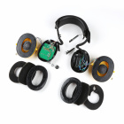
There is definitely room to grow this project. There always seems to be the next version on the horizon with more features :) Processing the sound to do some noise cancelling would be a fun new addition. With a slightly different setup on the signal path on the codec, you could route the mic signals to the ADC I2S "output" of the Codec, and then do some DSP on the ESP32 before combining it into the output. I would love to see how this works out, but honestly, I have been pretty impressed with the passive dampening of the larger ear-muffs.
About those ear muffs... yes, unfortunately, those exact "smoostart" ear muffs are no longer available. Just as we launched this tutorial. But there are quite a few like them out there. I'm guessing the motherboard would need some slight tweaking to match whatever new form factor is going on inside though.
I've also been looking at my ear muffs we use for construction that don't have any electronics in them. They just simply provide passive hearing protection. This pair I just looked up is really similar to what we have on hand for use in our house:
Decibel Defense Professional Safety Ear Muffs
These one's claim to have 37dB dampening, so that's even better than the smoostarts! And much cheaper than then most that have the unneeded radio/BT electronics inside. These come in two sizes - maybe the extra large would comfortably fit around my big ears.
I was thinking about designing another version of the "motherboard" that is as small as possible (maybe oval shaped), and then you could hopefully mount it inside any of these passive ear muffs. And so the project versions continue :)
If you do decide to build you're own, we'd love to hear about how it goes. And if you want to share, or run into any questions, please reach out in the new github discussions section of the tutorial.
Cheers! Pete
-
Hi 065, Thanks for asking. Yes, you can connect the HPL and HPR outputs to another sound system as a "line level signal". These will act as your un-balanced (aka "single-ended") line level signal outputs.
Note, it is common practice for a line level output (and some headphone amp outputs) to have output capacitors, however we did not include these on this breakout for optimal frequency response and size constraints. Most sound systems that you would plug into should have input capacitors, so in most cases you won't really need to add capacitors in-series to your signal. However, if you don't know if your downstream device has input capacitors, then you could add some in. Note, they will form an RC filter with the impedance of your downstream devices input, so usually it's a good idea to use large caps (47uF or 100uF), to ensure you still get good bass response.
If you'd like to learn more about the nuances involved with plugging in headphone outputs into line level outputs, then I can recommend searching google for "headphone output as line level". There are lots of great articles on the subject.
One more thought, if you'd like to make it a balanced audio signal (for more immunity to external noise and/or long distance), check out our SparkFun THAT 1646 OutSmarts Breakouts.
Hope this helps and good luck with your audio project! -Pete
-
Hey 773, Nice to hear from you! Indeed, the IC is a pretty darn cool facility. Everyone on their staff, the mentors and students are all wonderful to work with. It has been an honor to work with them on this project. I'm astonished by this team's dedication and how far they have come with their engineering skills. This was one heck of a huge PCB to layout and assemble by hand!
PS not sure if you saw saw these other posts over the past few years, but here are a couple more blogs we've done about the IC:
-
The ATMega328 has an internal oscillator. We program the fuse bits to utilize this at 8MHz. This is done in production just prior to programming the bootloader and Simon firmware. Hope this helps!
-
Thanks for your feedback. We will definitely consider the 1015 as a future project. It would be a drop in replacement on the PCB layout, and a minor addition to the Arduino Library, however, sourcing the modules (and all parts these days, really) is another challenge.
Also, I agree, most RC airplane's are flying much faster, and so it would most likely be only useful on thermal gliders and slow slope floaters (maybe some VTPR in lighter conditions, but even those could max it out on big dives). I've decided to remove that suggestion from the description for now. I might give this a try on my Ahi and report back.
