From 2009 to 2018 SparkFun hosted the Autonomous Vehicle Competition (AVC) where robotics enthusiasts came to our headquarters and tried to complete a course full of turns and obstacles. With accurate navigation being crucial for this competition, many methods of navigation were used to complete the course. Some utilized GPS, others programmed when to turn based on wheel rotations, and some even used a combination of distance sensors for obstacle avoidance to complete the course.
Looking back, I can’t help but think that if SparkFun’s Optical Tracking Odometry Sensor existed during our AVC years then that it would have been a big advantage for those who chose to use it in their robot. With odometry being a newer technology to bring to our catalog of sensors I wanted to better understand what exactly odometry is, why it was developed, and what its current and potential applications are.
What’s Odometry, Anyway?
Think of odometry as the GPS for robots and autonomous vehicles, but without relying on satellites. It's all about using data from motion sensors to figure out how far something has traveled. By tracking these movements, odometry helps in calculating the relative position of the vehicle, which is for navigation and mapping.
Pop quiz!
How have you been using odometry for years without probably realizing it?
Your computer mouse! A computer mouse measures its movement across a surface and translates that into cursor movement on a screen. The older mechanical mice had a ball inside that rolled as the mouse moved across a surface. This rolling motion was detected by sensors, which then calculated the distance and direction the mouse had traveled. This is similar to how odometry works by tracking the rotation of wheels to determine movement.
If you’re anything like me you’ll remember making the move from mechanical to optical mice. What a gamechanger! Optical mice use a light sensor to detect movement. The sensor takes thousands of images per second of the surface beneath the mouse and compares them to detect how far and in which direction the mouse has moved. This is akin to how optical odometry sensors work, using visual data to track movement.
Odometry Methods

Wheel encoders
Wheel encoders are a tried and true method where you can measure how much each wheel turns, and use this information to figure out the robot’s position. Sounds pretty simple. However, what if the wheel slips? Your measurements can be thrown off by how far the wheel spins, and not how far the robot moves. With the assumption that your wheel never slips, you can derive your position from as little as two encoders.
![]()
Using IMUs
IMUs track movement using accelerometers and gyroscopes, detecting changes in velocity and orientation. The level of sophistication, accuracy, size and affordability of IMUs has come a long way in the last few decades. Just take a look at the features of the SparkFun 9DoF IMU Breakout - ISM330DHCX, MMC5983MA. While versatile and useful in environments where wheel encoders may fail, IMUs can suffer from drift over time. Even the tiniest errors can accumulate and lead to larger positioning errors over time.

Optical odometry sensors
Optical odometry sensors, such as the SparkFun Optical Odometry sensor, use visual data to track movement across surfaces, providing high precision and reliability especially in situations where wheel encoders might slip. Unlike IMUs, optical sensors don’t experience drift but can be affected by changes in surface texture or lighting conditions.

Visual odometry
Visual odometry (often coupled with VSLAM—Visual Simultaneous Localization and Mapping) goes a step further by using cameras to track the movement of visual features in the environment to estimate motion. VSLAM not only provides odometry data but also builds a map of the environment; think robot vacuums. This method is powerful in complexity and dynamic environments where other sensors might fail, but it requires significant computational resources and can be sensitive to lighting changes, feature-rich environments, and camera calibration.

Sensor fusion
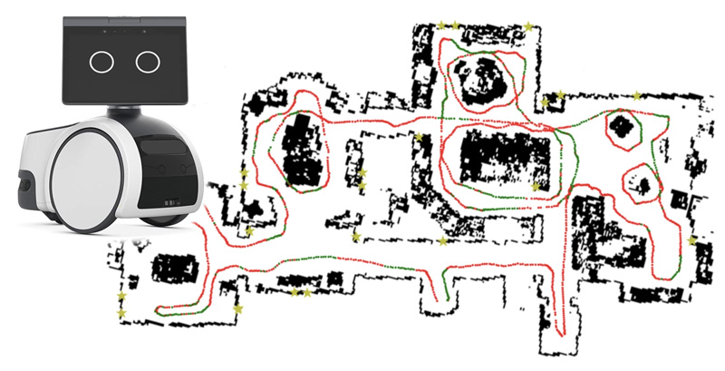
Combining these methods often results in the most robust and accurate odometry system. When one odometry method has challenges to overcome it can rely on feedback from another method for an accurate location. However, with any sensor fusion project, complexity is high, innovative algorithms are required and extraordinary computational power and memory are needed. I would recommend this great article on applying sensor fusion for odometry from 2020 about the Amazon Astro, a household robot for home monitoring.

Photo courtesy of Amazon.com
Meet the SparkFun Optical Tracking Odometry Sensor
- Super Accurate: The onboard chip offers exceptional tracking performance with error under 1% after quick calibration in ideal conditions.
- This sensor excels at high-speed motion tracking of up to 2.5 meters per second (5.6mph), making it an excellent choice for navigating warehouse robots, commercial robots, and other fast-moving applications.
- Space friendly: Measuring in at a mere 1in. by 1in. and boasts a smaller profile than its industry counterparts. Unlike bulkier options that require multiple boards, this sensor features a single-board design.
- User-Friendly: Nobody wants to spend hours setting up sensors. Thanks to its Qwiic compatibility, SparkFun made sure this one is easy to use and integrate into your projects. The included Arduino and Python libraries and the onboard tracking algorithm in the firmware streamline the development process, allowing you to focus on creating innovative robot functionalities.
There you have it, I hope you learned a little about odometry today! As we continue to explore and expand the applications of odometry, we hope tools like the Optical Tracking Odometry Sensor will play a role in shaping the future of autonomous technology.


