The word "hacking" as it pertains to hardware is often misused. In the commonly accepted definition, "hardware hacking" means modifying a piece of existing electronics to use it in a way that it was not necessarily intended. Even that definition is vague, as it can refer to any method of modifying hardware, be it the enclosure, the electronics, or the behavior. Modifying an enclosure of a device is usually straightforward; drill a hole, cut a slot, etc. But hacking the electronics and/or behavior is a complicated subject in itself. When looking to modify a device, sometimes it's hard to know where to start, and what angle of attack to take when hacking something for a purpose for which it was not designed.
If you're looking to hack a piece of hardware, how you approach the hack depends on what you're trying to do. Are you trying to make it wireless? Are you trying to change what it displays? Are you trying to get it to trigger another device? Each hack requires a different angle of attack, and it's difficult to decide on how to proceed if you've never hacked a device before. What follows are some common methods of hardware hacking and the implementations in which they are used. This is not, by any means, a "how to hack hardware" tutorial. Such an article could not exist in a complete form. The nature of hacking insists that there is always a new creative way to a solution, but these are some common methods that I've used in my experiences.
Method 1: Patching Into I/O
The first (and arguably easiest) method of hacking a device is patching into its control mechanism. Most consumer products have at least one button or indicator LED, and the connections for that component are usually easy to find and solder to.
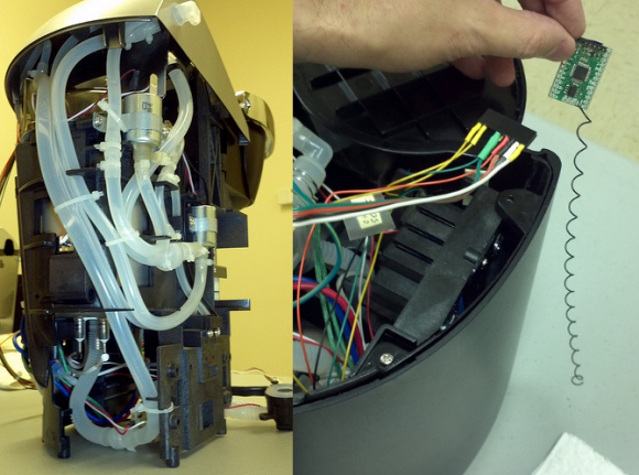
With access to button pads, you can attach your own button, relay, or transistor circuit to control it with your own hardware. For example, if you wanted to make a device wireless, you can connect your wireless device directly to the button pads to drive the button signal high or low depending on what the wireless device receives. I see this kind of implementation all the time. For example, there was recently a write-up on hackaday about a user named Kolumkilli hacking his Keurig coffee maker to be wirelessly controlled. He accomplished this by locating the "brew" button pads and connecting a wireless device. This kind of hack can be accomplished without digging into the actual programming of the device.
Image courtesy of Hackaday
With access to the LED pads on a device, you have a reliable output source from the device. The best example I've seen of this is a hack with the Star Wars Force Trainer. It appears the blog post for this hack has been removed, but in the hack the designers simply soldered to LEDs on the base of the toy to trigger their own device when certain LEDs turned on. Then they could use the toy as the controller for their own system, without ever having to access the data on the device.
Image courtesy of starwars.com
Method 2: Replacing a Component
This method is often used in Circuit Bending. The user wants the device to sound different, so he or she replaces a component (usually experimentally) to get a different sound out of a device. This kind of approach isn't relegated to Circuit Bending, though. A lot of interesting hacks have been achieved by replacing a component. For example, replacing bike light bulbs with high-intensity LEDs, or replacing the motors on an off-the-shelf toy car to make it drive dangerously fast.
Image courtesy of Hackedgadgets.com
Method 3: The Logic Analyzer
One can gather a lot of "private" data from a device with the use of a simple logic analyzer. To do this, one finds an interesting chip or test point on a circuit board, connects a logic analyzer, and then runs the device. The logic analyzer will record any signals occurring on the lines it's sniffing, and that data can potentially be translated into something useful. I once hacked a Lidar range finder this way, probing its serial lines while it was running.
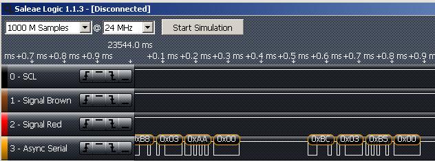
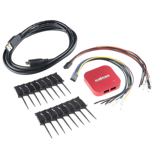
The blog post went live before I had time to do anything useful with the data, but I made the data public, and by the next day someone had interpreted it and created of video of the graphical representation of the data. Just for a little shameless self-promotion, I used the Logic Analyzer that we sell, which does auto baud-rate detection and signal translation for the SPI, I2C, and serial protocols. Because of this, it is a vital tool in my hardware hacking toolkit.
Method 4: JTAG Hex Dump (a.k.a. Voodoo)
When an electronic device is manufactured, it must be programmed with firmware at some point. The same port through which a device is programmed can also be used to disassemble and hack the firmware. Many microcontrollers have a memory dump feature that can be triggered through its programming port that allows a user to read the full memory (in hex) of the chip. Many devices include a feature that "locks" the device so that it cannot be read or reprogrammed once it is flashed, but many device manufacturers do not implement this feature, leaving their products susceptible to firmware hacking.
In order to hack firmware through a programming port, one must:
- Identify the device and if it has the capability to dump its memory
- Build or buy a programmer that can receive this memory dump and transmit to a computer
- Get the hex dump from the chip with the programmer
- Disassemble the hex into assembly language
Once the hacker has the assembly language, he or she is looking at the firmware. From there one can modify the firmware file to one's own ends, changing variables and registers to change the behavior of the device. Then the hacker recompiles the firmware into hex, and reprograms the device with the hacked firmware. This is an advanced method of hardware hacking, but can provide the most effective (or entertaining) results.
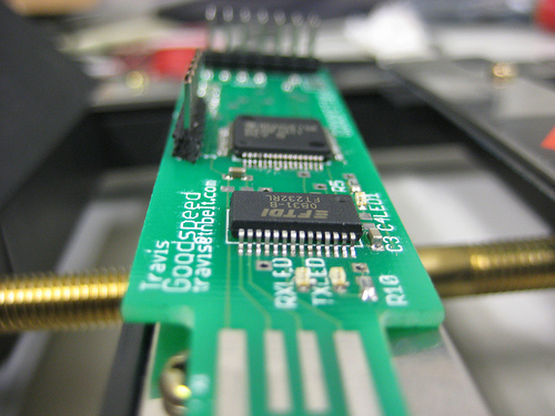
One of my favorite examples of this sort of hacking is the GoodFET, a device developed by Travis Goodspeed to (among other things) easily trigger a hex dump and re-flash the memory of multiple platforms (MSP430, AVR, PIC, etc.). The GoodFET makes it easy for the hardware hacker to download or "peek" at code hosted on a chip, in order to modify or exploit it for hacking.
Image courtesy of Goodfet.sourceforge.net
For those interested in heavy-duty hardware hacking, be sure to check out Travis Goodspeed's blog.
As I said before, this is by no means a complete "how to hack hardware" article. There will always be new ways to modify and hack new devices and chips, and someone will always come up with some slick way to use a device to an unintended end. What methods have you used to hack hardware, or what do you find useful in the reverse engineering process?




Isn't there the "Replace the controlller" method? Yank out all of the chippy insides of a device, and replace it with your own.
I would consider this the extreme example of case-modding. I've certainly gutted my fair share of toys to make them do something strange and/or terrible.
I am thinking about eventually doing this to my (now out of warranty) washer and drier.
This would never work. IC manufactures do some pretty interesting security to lock the IC down from being reverse engineered. So yanking a chip and replacing it won't do anything but cause more headaches.
I wasn't thinking replace just the chip. I was thinking of replacing the entire controller board!
How would that work? I don't see it ever working even from a remote controller to a PLC system.
Say you had a toy, like maybe a remote controlled car you wanted to run autonomously. Wouldn't it be possible to yank out the receiver and and any other electronics other than the motors and servos?
Then add your controller board with it's own motor drivers, attach extra sensors, and what not.
I agree with CTaylor, and that this is really case modding.
Also useful for hardware hackers: see my tip on how to find schematics, wiring diagrams, and other detailed info on anything that has a FCC ID: https://www.youtube.com/watch?v=t5ivz3KKszk
Whoa, awesome!
Thanks for the article. It reminded me of the days when I was developing BBS software on Atari 8-bit computers, and had an Atari 1030 modem, which had autodial but no auto-answer feature. To make the BBS able to answer the phone, one had to build a 'ring detector' circuit which threw a relay's contacts when the phone rang. Those relay contacts were wired to a joystick port's "fire button" pins. The BBS code would poll in a loop waiting for the 'fire' button to be pressed, then send a command to the 1030 modem to pick up the phone in answer(host) mode. It worked like a charm for those who dared to hook non-FCC approved devices to the public switched telephone network.
This brings back some memories for me. I'm probably going to date myself a little but I remember as a young teenager going through the HUGE 18" x 9" x 3" thick Computer Shopper magazine and finding ads for BBS numbers, waiting for my parents to go to work, and then spend most of the day checking out the different BBS'. I am like brennen, I missed out on the days of programming for BBS, but I remember having to call 20 different BBS sites to find that 'one article that talked about this'. Ahhh, the good old days. Those were also the days of looking through the ads and seeing one for a 1 GB hard drive, and the thought through my head at the time was "What on earth would you need that much data storage for?"
This is fascinating stuff. I'd love to read a longer writeup.
I was just playing around last night with listings on the BBS Corner. All of the places I logged into were basically ghost towns, but there are a surprising number still in service.
I pretty much missed out on the BBS era as a kid - we were too far out in the boonies for there to be anything local, and my parents watched the phone bill like hawks. If I had it to do over again, I'd run one of my own. Lately I've been thinking about how much fun it could be to run one at SparkFun. Even better if it involved some hardware hackery...
The software in question was a heavily modified version of Fast-AMIS (Atari Message Information System), it was initially developed by a user group in Michigan. A friend and I decided to modify it to support multiple message bases (i.e. forums) because it only had email and a single public message store. The code used nearly every available byte on a 48k Atari 800 (with the BASIC cartridge installed), so we couldn't afford to duplicate any code to establish more public message areas. We had to dig deeply into the code and create our own custom message header scheme to partition the message base. We also added XMODEM file transfer routines because the original code only supported ASCII file transfers. To test our code, my cousin decided to operate the BBS from his house. You may find old listings for it, the "Grimoire" BBS in Zelienople, Pennsylvania.
The original AMIS software from M.A.C.E. (Michigan Atari Computer Enthusiasts) was coded to poll joystick port 2 on an Atari 8-bit computer. So, you could literally plug a joystick into that port, wait for the phone to ring, then press the fire button.. and your BBS software would direct the modem to answer the phone and then fall into its 'online' processing routines. To automate the pressing of said fire button, a simple 'ring detector' device could be built. It was essentially a 20uF 70V cap and a 125V AC relay. You would connect the phone's green wire to one side of the relay coil, connect the phone's red wire to the negative side of the cap, and the positive side of the cap to the other side of the relay coil. Then you would take a joystick and cut its cable (keeping the end with the 9-pin connector). The joystick connector plugged into joystick port 2 of the computer, and on the other end you'd connect the 2 wires for the fire button to the relay contacts (orange wire to the relay common terminal, black wire to the relay's normally open contact). When the phone rang, the relay would switch on and press the 'fire' button. The BBS would detect this and send the command to take the modem 'off hook' (thus ending the ringing) and send an answer-mode carrier tone which began the old dialup modem handshake process, and the rest is history.
Again, the reason for all of this workaround was that the commonly available modems of the day (Atari 835 and Atari 1030) had no auto-answer feature.
In my opinion Method 1 and Method 3 are the best ones to use on reverse engineering a black box system. Method 4 is nice, if the chip does debug communication through JTAG. (As for FPGAs, once the chip is programmed through JTAG, it will not blindly send data to JTAG unless there's a debug core in it).
In a world of digital signals, a logic analyzer is your best friend on analyzing EVERYTHING. With some LAs having upwards of 32 channels, you can build a very nice waveform that you can monitor. If the system has user inputs, tie the LA to all the signals you can, and start systematically pressing buttons. This way you can build a behavior model which you can then analyze and use.
Is assembly language the highest level language you can get dumped? Just curious.
This was an awesome read - Not sure if anyone would be interested in the Green Bean hacker chip but it allows you to hack your appliances like your fridge and make them smarter. Here is a link if you want to check it out... http://bit.ly/1bgreenbean
A hacker is an adherent of the subculture that orig hacker is someone who loves to program or who enjoys playful cleverness,or a combination of the two.The act of engaging in activities such as programming or other media in a spirit of playfulness and exploration is termed hacking. http://passforsure.co/312-50v8.php
i had seen one the episode of 'the big bang theory'. in that episode, the guys were able to switch off and on the lights in a home at any part of the world through Internet. Is that hardware hacking???
Is this a type of "Method 1" hacking?
http://cheezburger.com/7879559168
Hey CTaylor: This link (http://www.solidstatedepot.com) on your profile is bad. Should it be more like http://boulderhackerspace.com/ ??
Thanks for the heads up! I still want it to be the old URL. If only I could get ahold of Dan...
:) Nice article btw..
Not sure it counts as "hacking" but you forgot a very important option: Beg the OEM for docs. This can be surprisingly effective with the right contacts.
Years ago I purchased several POS (point of sale) displays. These are large dual-sided 2x20 VFD displays that mount to a pole as part of a cash register system. Communication used an RS-485 interface and while others had managed to figure out some of the commands, I wanted full control of the display. The device uses POSLAN protocol, which wasn't available publically. The board was 8051 based, using internal flash, but there was also a 28-pin ROM socket available on the board. By grounding the EA line I could run code from the external ROM, rather then the internal FLASH. Once my code was running, it copied itself to RAM, jumped to RAM and continued running. Now it switched the memory back to internal FLASH and performed a ROM dump out the serial port. I captured this output and was able to disassemble the code and modified it into a simple terminal program that used both sides of the display.