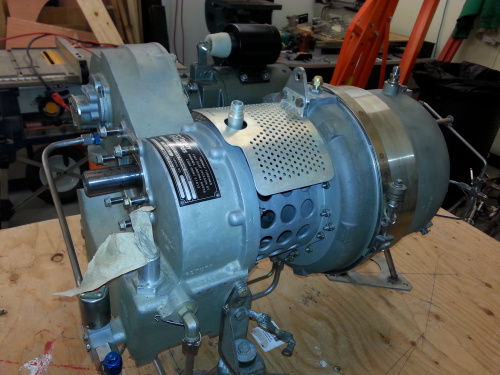
Nearly a year ago I made a terrible mistake - I bought a jet engine. So what have I done with it? Well not too much unfortunately. But I do have some progress and a few things learned along the way.
I last left us with a picture of a jet engine sitting on a table and all the excitement and anticipation of great things to come.
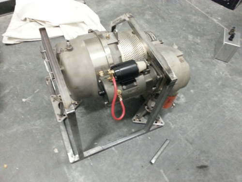
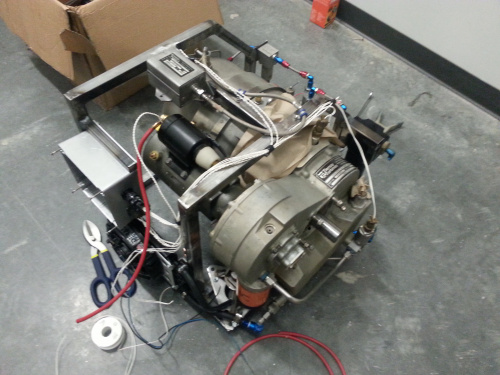
For starters I decided to build a small frame to house the engine and hold all the supporting components. For this build, I first started the design in a CAD program but quickly found myself in a state of "paralysis by analysis." I continued to fiddle with placement of components and tried to characterize how every wire and tube would route. This became tedious enough that I turned to my roots of building.
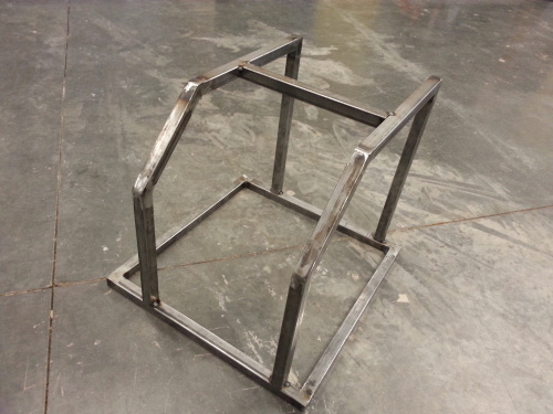
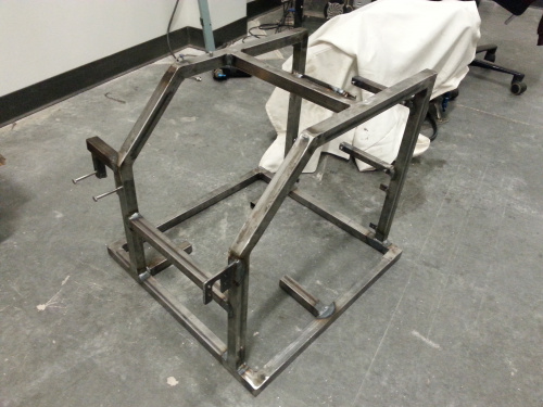
Starting with some square tube I began to chop, weld, grind, weld, re-grind, come to terms that I am not a welder, then grind some more.
Using the floor and some masking tape as my template I slowly cut and welded until a frame took shape. It's not pretty but I managed to make something that will work for now.
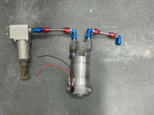
Once the frame was built and most of the parts were test fitted, I began to plumb the system. On paper this was easy but in practice it was a tedious affair. The difficulty was in finding the proper connectors that are used on the engine. Luckily I had some help from our resident racing enthusiast, Pearce, who helped me identify that the connectors were AN fittings. And with that piece of the puzzle solved I was off looking on auto parts sites to come up with a myriad of ways to make all the connections I needed.
Plumbing is complete. Now I just need to get the electronics built up. This is the area I am currently researching. There are a few major components I need to address.
- Starter - Starts the engine, consumes about 100-150amps
- Igniter - Starts a small controlled fire in the engine, I'm still afraid of it
- Fuel pump - Adjusts fuel pressure to the engine
- Fuel Switch - Safety feature to kill the engine before it kills us
- Thermocouple - Tells us how hot the engine is
- Speed sensor - Tells us how fast we are spinning
- Oil pressure sensor - Tells us that oil is still flowing
So far the only components I have gotten working are the starter and the speed sensor. The starter is very simple - you apply power to the starter solenoid and away it goes. The speed sensor proved to be a bit more challenging. The speed sensor uses a similar technology to electric guitar pickups. It uses a sensor method called a variable reluctance. Instead of a standard pulse output, a sine wave is produced with a voltage of about +/- 10V at peak RPM. I will need to devise a circuit to convert this to a square wave that can be read in by an Arduino.
While my progress has been slow it will continue. I hope to have a working demo for some of our upcomming events. I have put the build on temporary hold since robot season is in full swing. But that's another post.



Have you thought about building one of these for the upcoming AVC? http://www.asciimation.co.nz/beer/
That is my favorite brand of awesomeness: Crazy.
Use a MAX9924 for your VR conditioner. It's designed for it and works great.
This is great! I am absolutely going to get this.
I hate to be the word nazi, but this is not a jet engine. This is a gas turbine, specifically for driving generators or hydraulic pumps. While a jet engine is a gas turbine, a jet engine develops thrust at the exit. Not all gas turbines are jet engines of course.
This engine produces about 20lbs of thrust. But yes you are right, it's a gas turbine. In my first post I point this out.
Look into 'zero crossing detector' circuits for your sine wave conversion.
The fuel shutoff switch is also important during the start of a turbine engine. No fuel is to be delivered before the turbine is at the start RPM, with ignitors on. Otherwise the engine can start with a bang. (This is bad news when it happens.)
Very cool! I literally got into building my own digital electronics about 15 years ago because I needed to build a tachometer for my own jet engine (was building one from a turbocharger). I've since bought many commercial engines myself, including a Boeing 502-6 turboshaft (160shp) and my big one, a T53 out of a Huey helicopter, good for about 860 shp. I've got them on my site... nuclearprojects.com
Curious as to the power of this jet engine and/or a part number. Is it from an APU? if so, what is the rating of the generator output? Also curious where the speed sensor is; assuming it is on one of the shafts after some gear reduction and not on the actual turbine rotor shaft that I read can hit 100,000 rpm or more.
It's a Tiernay TT10, 10kW power generator, good for around 20-30hp, not real powerful, but does the job it was designed for. I don't know the tach on this one, but most(all?) commercial engines have a tach generator that is mechanically connected to the engine through gearing. It's output is proportional to the % rpm of the engine. I've had several commercial turbine engines myself (T53, Boeing 502-6, etc.)
The 20-30hp number comes from the inefficiency of the generator. The engine itself is capable of producing HP in the 80-100 range (when new). There are people using engines similar to this in light aircraft.
The thermocouple isn't just there to monitor how hot the engine is. The Exhaust Gas Temperature (EGT) thermocouple can also be used as a shutdown (engine too hot). In most cases the EGT Thermocouple also forms part of the control algorithm (EGT Limiter). It is a relatively simple control loop, let me know if you need more detail.
Yes, one of the thermocouple amps I'm looking at has an overtemp setting. This will connect to the fuel shutoff valve to kill the engine if temperatures exceed spec.
O and heads up I know your not there yet but once you start using the engine keep an eye out on the welds cause jet engines as you know are powerful and can cause a lot of vibration and we all know vibrations will start cracks in welds.
Please tell me this is related to the shortcut. Fight through jet wash to save a little time.
Also, on the topic of an oil pressure sensor, I've had luck with Bosch/Sunpro 7577 oil pressure sender unit. They're <$10 and can be interfaced to an Arduino with a simple resistive divider.
Any idea how high of a pressure the Bosch/Sunpro 7577 sender can read? Since replacing the 7 HP motor on my air compressor with a 3 phase motor and VFD, I am a bit worried what might happen if the motor fails to turn off, and would like to add some redundant protection circuits...
If you would rather have an analog signal to deal with, TI offers the LM2907 for taking VR outputs straight to analog signals.
Don't know about this engine, but the aeroderived turbines we use in generators in oil platforms need some care when starting up... you have to obey a ramp regime and also skip some resonance speeds. I'll see if I can find good bibliography on the control and care of gas turbines!
I have a feeling next year's AVC is going to be awesome.
Or this year? :)
Ahah is this the shortcut obstacle ? :D
This might help for picking up the Variable reluctance. I built this for controlling my car's engine timing - which picked up the crank signal from a variable reluctance. Worked really well.
https://thedeltaecho.wordpress.com/2010/07/02/crank-signal-input-detection-logic/ https://thedeltaecho.wordpress.com/2010/03/14/2jz-ge-cam-crank-signals/ https://thedeltaecho.wordpress.com/2010/03/17/cam-crank-signal-outputs/
Good luck and keep us posted! I was wondering what would come of this project. :)
In order to change the sine wave into a square wave, could you use an op amp comparator that outputs either VCC or 0 based on whether the sine wave is above or below 0?
Might be able to force a CMOS device to handle this. I would probably just use a 5V zener and a regular diode to block the negative half. Then feed that to a Schmitt trigger gate.
This is what I was thinking, but didn't know it. http://talkingelectronics.com/pay/BEC-2/Page49.html