William Premerlani started the MatrixPilot open source autopilot project in 2009 and has been a regular contributor to the state of the art of do it yourself drones since then. He has collaborated with SparkFun on the design of the UAV development board, which is presently in its 5th revision. Several of his technical discussions can be found here.
Since 2009, SparkFun has offered various versions of its UAV Development Board. We are presently selling version UDB5. Free, open source software for the UDB is developed in the MatrixPilot project. Recently the MatrixPilot team completed and tested new control firmware for fixed wing aircraft. It works quite nicely, so we thought you might like to hear about it.
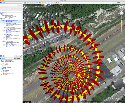
The basic idea is to produce a helical trajectory, shown in the following figure in the general case, which includes circles and portions of circles in specific cases:
Helical Trajectory. Image Credit: Peter Hollands, MatrixPilot Project.
For the last year or so, Peter Hollands and I worked to develop a "helical turn control" for MatrixPilot, using basic principles. One goal of the new controls was to be able to fly an arbitrary helical trajectory. Peter had some fun producing the above trajectory using XPlane-10 and HILSIM, running the latest version of fixed wing flight controls for the open source MatrixPilot project.
Check out Peter's great demo video of the new controls:
ReplaceMeOpen
ReplaceMeClose
You can also read additional info on the DIY Drones blog about this test run.
The theory of helical turn controls is described in the following three documents:
The first document, Helical Turns Part 1, describes the conditions that need to be satisfied to achieve a coordinated helical turn.
The second document, Helical Turns Part 2, describes a simple controller, relying mainly on feedforward and proportional feedback to satisfy the turn conditions using matrix-vector computations.
The third document, Helical Turns Part 3, describes a method for accounting for angle of attack and variation of elevator trim with wing loading and airspeed. Required model parameters are computed automatically from flight data using a program that Peter Hollands wrote.
Helical turn controls have been thoroughly flight tested for over a year, and have been found to perform quite well, including the following advantages:
Tight, smooth, aggressive turns in both normal and inverted flight. For an airplane with ailerons, the controls can put the aircraft into a turn in less than 1/4 second, and can provide stable control with a turn rate up to the limits of the ranges of the gyros and accelerometers.
Level flight during a 180 degree roll over from normal to inverted flight.
Easier low speed hand launches because the controls automatically adjust angle of attack and elevator trim for changing airspeed.
Projection of earth frame pitch control onto body frame control surfaces, so pitch control is maintained in any orientation, including knife edge, or during a slow roll.
Elimination of the need for integral feedback. Using helical turn control, a combination of feedforward and proportional feedback performs better than conventional PID feedback control. This simplifies the selection of gains. The controls work well over a wide range of proportional feedback gain settings.
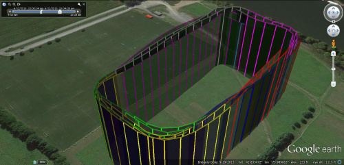
Here are a few pictures from recent actual flight testing with my EasyStar. First, a few circuits around a rectangle in waypoint mode are shown. Please note that some of the flight segments and turns were flown inverted:
Flight Track of the EasyStar. Image Credit: Bill Premerlani
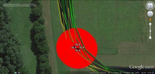
Next, a close up of the tracks through waypoint 4. Note that there are many tracks and they are all within a few feet of the waypoint, in all three directions:
Fourth waypoint on the flight pattern. Image Credit: Bill Premerlani
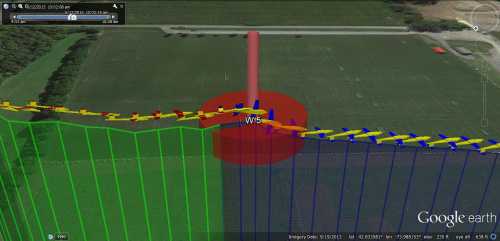
Finally, a view of a 180 degree roll over from normal to inverted. Note that the controls automatically account for the reversal in sign of the wing loading and adjust the angle of attack and elevator trim to maintain level flight. You can see that the plane quickly pitches up a bit once it becomes inverted:
Waypoint showing flight inversion. Image Credit: Bill Premerlani
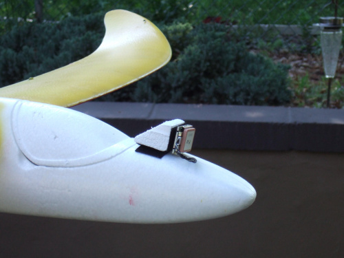
By the way, one problem that I ran into during inverted flight was that the EM506 GPS that he was using stopped working when it was pointed toward the ground. A friend of mine, Robert Pixley, suggested a solution: Mount the GPS vertically instead of horizontally:
Vertical GPS Mount. Image Credit: Bill Premerlani
It was found that with a horizontally-mounted GPS, there were typically 10 or 11 satellites in view during normal flight, and at most 4 in view during inverted flight. With the vertical mount, there were 8 or 9 satellites in view all of the time.
Thanks to all of the MatrixPilot developers and users who helped with this. Here are a few links for those of you who might be interested in the MatrixPilot project:
- MatrixPilot project home page. (Note: This will be transitioning to GitHub here due to Google Code changes).
- UAV Development Board available from SparkFun.
- Helical turn controls firmware.
Finally, you can read about the history of the first four versions of the UAVDevboard here.


Wow, I'm going to try vertical on my quad copter now! thanks for the information. I'm curious about this board now.
the GPS mouting strategie is interesting! Mounting on gimbal would help but add weight. Double GPS with different orientation would add redundancy but would cost more.
Robomaniac, The vertical GPS mounting strategy worked better than I thought it would. I thought that changing from horizontal mounting of the EM506 to vertical mounting would cause the number of satellites in view to drop by 4 or 5, but it only dropped by 1 or 2. So far I have made about a dozen inverted flights with the vertical mounting with consistent, reliable results. Best regards, Bill