Big thanks to David Holshouser for geeking out with us about COSMOS, and sharing Ball's history with the project!
As the Internet of Things brings in more folks from the coding world to the embedded world, the language and interface options for programming your embedded devices continues to grow. Ruby isn't typically a language that comes to mind first for embedded device interfaces, but that doesn't mean it is any less capable.
Enter COSMOS. This is an interface system designed to allow for testing, debugging, and real-time control of embedded systems, as well as data collection and visualization, and uses Ruby as the main framework. The fine folks at Ball Aerospace developed this program several years ago and have been using it for their own projects. Some of the projects that have been worked on using COSMOS include the following:
- Kepler Sattelite - A big shiny satellite for NASA
- WISE spacecraft
- STORRM- Navigation system for the International Space Station
- Startrackers - Orientation equipment for satellites
- MOIRE - Membrane Optic Imager Real-Time Exploitation
- Orion VNS - Vision Navigation
Other projects outside of Ball have also used the COSMOS system for development, including NASA’s IceCube CubeSat. The TrapSat project also has used this in the development and testing of their trash-collecting CubeSat, and Blue Canyon Technologies uses this as a test system for their Spacecraft Buses.
The list goes on, but you get the point. This tool is being used in a lot of BIG applications. It turns out though, it’s also a great interface for embedded electronics like everyone’s favorite Arduino. I don’t know about you, but my excitement level for tools definitely increases if I know that rocket scientists are also using them (Space Pen, anyone?).
There isn't much documentation available currently for interfacing this with DIY widgets and electronics, but that is also hopefully beginning to change. Ball open-sourced the entire platform last year, and the source code is available on GitHub, giving you the opportunity to fork it for your own purposes, or collaborate with the team fixing issues. A small group of folks down the road at the local Boulder Ball office are also starting to play with this with electronics from their local "hackerspace library." With the library of tools and equipment that can be checked out and used for personal projects, there are some really fabulous projects coming to life.
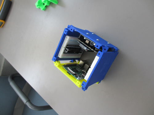
Jim Velasquez is working on his own personal CubeSat, and has been using COSMOS for programming and testing his design. His CubeSat is running with a Raspberry Pi.
Image courtesy of: Jim Velasquez
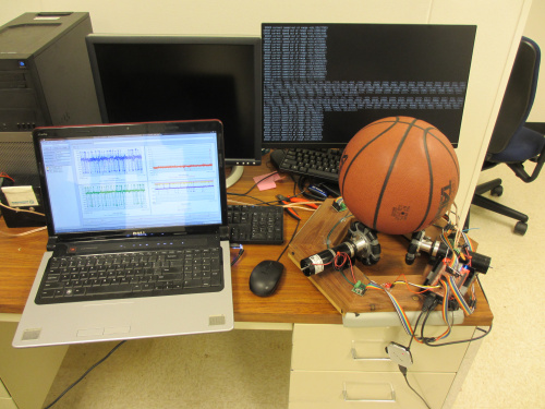
Sam Povilus is also using COSMOS for testing and configuring his ball-balancing robot. He can also view the data output graphically in real-time from the accelerometer and gyroscope for additional debugging.
Image courtesy of: Sam Povilus
If you’d like to play around with the code Sam is using, it’s available on GitHub.
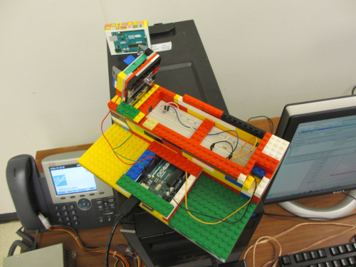
Another project is the Lego LED/Photodiode system built by Kevin Farley (with Lego assembly help courtesy of his kid).
Image courtesy of Kevin Farley
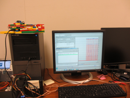
This project encodes messages as a series of LED blinks that are registered by the photodiode. COSMOS makes it very easy to track the messages being sent, and debug the system if something goes wrong.
COSMOS sending commands and receiving photodiode data from an Arduino. Image courtesy of Kevin Farley
The Platform Itself
So enough of the flashy projects that have been built on this platform. What about the actual meat and potatoes of it?
First of many features is that this system is cross-platform compatible. There are batch installers for Windows, Linux, and Mac, and it really does install very quickly and easily (at least in my tests on Linux and Windows). I went into each install with baited breath because the words “open-source software” and “easy install without bugs” don’t generally go together in my experience, but in this case, they did.
Additionally, the code syntax in general was very easy to pick up. Not being familiar with Ruby myself, I was expecting to be spending a lot of time digging into the manuals to figure out the formatting and syntax, but overall, it came relatively easily. While I didn't have a chance to dig in and explore this feature more, one upside to COSMOS being written in Ruby means that if you need custom drivers for a particular piece of hardware that isn’t already supported, you can write those up and simply use them as plugins (though there is already support for serial, TCP/IP, and UDP out of the box).
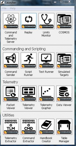
When you first launch the program, you're provided with a lot of options that can look a bit overwhelming, especially if you are coming at this fresh from Arduino land.
COSMOS Application Launcher Window
Luckily, there’s a pretty great overview of the whole program here, with basic explanations of what each application does, making it easy to dive in and start playing around with the program. There’s also a YouTube video demo of each application, for those of you who prefer watching to reading.
David Holshouser has also written a wonderful beginner guide for the classic "Blink" application. You can work through his example here, which also leads into some cool window configuration options for COSMOS.
Following his guide, I was able to get basic control of an LED on my Redboard relatively quickly, blinking it along at variable rates that I could control through the Command Sender and Telemetry viewer window. One problem that I did run into that made for a frustrating day of digging deep into the code backend was the fact that attempting to set this up on an old Redboard (Version 1.0) with an FT232 IC on it led to a lot of errors being thrown by COSMOS each time I attempted to run the the program. In the end, the Reboard wasn't registering on the COM port (despite programming just fine in Arduino), but I kept receiving syntax errors on things like "NONE" being an invalid parity type. Thank goodness for open-source code allowing me to RTFM to confirm I hadn't been doing that wrong all these years.
After a simple swap to a newer board, the compiler errors disappeared and I was able to get into the fun part of hacking the cmd.txt, tlm.txt, and cmd_tlm_server.txt files, which are the command, telemetry, and command telemetry server configurations, respectively. I wanted to see how easy it would be to start taking analog data in and logging it (as the logging capabilities of COSMOS are also pretty phenomenal).
If you'd like to see my updated code for this, my files are available here.
In keeping with the Blink/Hello World vein, I wanted to translate the default Arduino example sketch ReadAnalogVoltage.ino. I started by configuring COSMOS.
To graph all the analog readings coming in, I set the following in_ tlm.txt_:
APPEND_ITEM analogReading 8 UINT "Current analog reading"
which tells COSMOS to set up a basic telemetry slot for the analog reading the Arduino will be sending back. To test sending the commands to the Arduino, I also wanted to be able to change the pin declaration in COSMOS, and have Arduino return data readings from the pin of my whim at that moment.
In cmd.txt:
APPEND_PARAMETER readAnalogPin 8 UINT 0 19 15 "Analog pin to read"
sets COSMOS up to allow me to send a new command of an analog pin definition. (I used the standard pin names for the ATMega328 instead of the Arduino definitions, so A0-A6 are identified by 14-19 in COSMOS.) As with the analog reading telemetry setting, adding the following to tlm.txt:
APPEND_ITEM readAnalogPin 8 UINT "Current analog pin"
which then allows me to track which pin the Arduino is currently reading.
My Arduino sketch ReadAnalog.ino also had to be updated to ensure the Arduino can receive all the commands coming from COSMOS, and send back the proper information for logging.
    //Create structure for the COSMOS commands/telemetry
struct analogVal
{
  byte msgSize; //Packet length for COSMOS (COSMOS item 'length')
  byte id; //Command Identifier for COSMOS (COSMOS item id)
  byte pinID; //ATMega328 pin to read (COSMOS item 'readAnalogPin')
  byte reading; //Analog reading (COSMOS item 'analogReading')
  byte cmdsReceived; //Number of commands received from COSMOS (COSMOS item 'cmdsSent')
  byte cmdsAccepted; //Number of commands actually used from COSMOS (COSMOS item 'cmdsAccepted')
};
Appending each item to the data structure was an easy translation from the COSMOS configuration files.
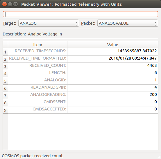
Running the Command and Telemetry application, I can see my data is set up and the Arduino is communicating with COSMOS.
Packet Telemetry viewer showing there are packets moving between the Redboard and COSMOS.
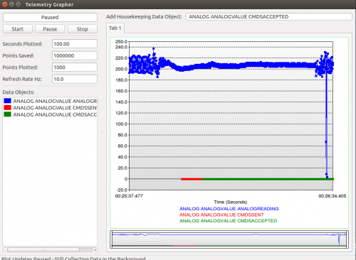
Pulling up the graphs, you can view not only the analog data coming in, but also the number of commands sent to the Redboard, and the number the Redboard has accepted. If all is peachy, those should match.
You can see the analog readings vary as I fiddle with the pins being read.
In the previous screenshot, COSMOS isn't showing any commands being sent or accepted, which makes sense. I haven't told the Redboard to start reading a different pin than the one declared in the setup loop in the .ino sketch.
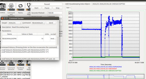
Once a few pin swaps have been sent, you can see the data changing real time to reflect the new pins being read, as well as the number of commands being sent and received starting to tick up.
Analog readings fluctuate widely as the pin being read changes.
Pretty easy and straight forward! While I didn't have nearly enough time for this blog post to dig into the program as far as I wanted, it's an interesting tool to have available for graphing options. I personally thing it would be a great option to use with things like the CAN-Bus Shield or the OBD-II UART Board, where data logging and real-time graphs could be of great use.
One other thing to note if you decide to play around with COSMOS – it does log a lot of data as you go. These files can quickly reach and exceed the file size limits for things like GitHub, so consider setting up a .gitignore file early if you don't care about saving the log data and intend to share your work online.
If you've had a chance to spin up your own project using COSMOS, let us know below. Or if you have feedback on COSMOS itself, head over to GitHub and ping the Ball Aerospace team!





Thanks for the great writeup. My name is Ryan Melton and I've been developing Ball Aerospace COSMOS for about 9 years now. If anyone has any questions, please feel free to ask. I believe it can be really helpful to the Sparkfun community by providing a user interface for their embedded systems. Where it really shines is in hooking together multiple systems.
Ryan -
This looks pretty interesting, I am trying to figure out if it's the right solution for my need - let me explain.
I manage 14 unmanned, remote sites that have some SCADA type monitoring - mostly alarm contacts, such as hight temp/ low temp. What I can't see is where the temp actually is - just that it's in alarm. For most of the alarm points (smoke detectors, door sensors, etc.) this is fine, but I am looking at adding a separate system that allows me more flexibility - Arduino's talking to 1-wire sensors attached to a Raspberry Pi is one way I am thinking. Perhaps 5-8 temp sensors monitoring the air temp of the redundant HVAC systems, outdoor temp, and some in equipment racks , a few DC voltages to track, maybe a couple of other things, but gathering and tracking the data across multiple sites starts to become daunting. COSMOS looks like it might be the right fit to track and manage all these datastreams from multiple sites, and watch ranges / alarm on sets out of range.
Looking for more info - the documentation has lots on COSMOS, but how do I talk to a RPi with it? Is there a program that runs on the RPi that I am missing?
Thanks!
The short answer is, yes. COSMOS is an excellent tool to view and control remote devices of any kind. With a little configuration, you can visualize, post-process, log, graph, or write smart scripts to automatically respond to different circumstances, like your description of responding to alarms about temperatures out of limits. This is exactly what COSMOS was written for and how we use it everyday.
COSMOS is a generic controller interface and comes with I/O defined for different kinds of communications protocols, like serial and TCPIP.
To talk to your RPi, you'd just need to setup the TCPIP connection and define your packets in the COSMOS config. Building the packets on the RPi and putting them out a socket is up to you.
There is an example mentioned in the original blog post which uses direct serial to talk to an Arduino. The point of the example is to show the simplest hook-up from a target (the Arduino) to COSMOS. In that case I used serial because it's so easy with the Arduino and outputting the data only added a few lines of code in the sketch.
In your case, all you need to do to connect to a RPi is define your COSMOS cmd_tlm_server.txt with tcpip_client_interface.rb in the INTERFACE line. Once your RPi is sending data out the socket, COSMOS will read the TCPIP stream and turn it into packets so you can see your data on the PC.
Can I communicate RPi to COSMOS using serial too?
So, my RPi fu is kinda weak, but the answer is yes.
I'm not sure if the USB ports on the RPi have a direct serial out or if you have to use the serial Tx/Rx pins on the GPIO connector. I'll leave that as an exercise for you, but check out the USB to TTL Serial cable and see if it gives you the serial link you need.
Once you have a serial line from the RPi to the PC running COSMOS, all you have to do is setup your interface like the example above to the correct port on your PC and you're off to the races.
See the Configure the Input / Output interface section in the example.
Hello, can somebody please help me with the installation of the software? I don't know much about programming but i need the program to use it as a telemetry interface for a project. I need help!
Unfortunately, Toni (the author) has since moved on and this software isn't something we really assist with (we didn't create it). Please see the comment above or check out the GitHub repository for more help.
FYI, the ball balancing robot is in the wrong order, the ball should be below the robot, not above. I had it like that for debugging(Convenient place to store the ball).
COSMOS is an awesome tool set, with lots of applications for the build and test of embedded products as well as for IoT command and control. I could see the clever folks at SparkFun using this with those killer pogo pin test fixtures they make- as part of an automated test facility that we all hope they need someday (because they're making so many awesome products!!)
One comment about the cubesat looking thing above (it's roughly correct 1U cubesat dimensions).
That is a TinkerSat- a platform for making it easy to teach embedded device / IoT which came about through discussions with my fellow members of the tinkermill.org makerspace. It's not really intended to fly in space.
It's designed to allow you to roll up a collection of plates that could hold embedded devices, breadboards, jumper wires ant the like into a convienient-to-carry and cool looking little package. At present there are plates to hold breadboards, Arduinos of various flavors, and Raspberry Pi. I'm about to build a plate that mounts a Photon, and maybe an Edison as well.
One thing I hear constantly about people wanting to come work on embedded systems/ IoT at TinkerMill is that they only have limited time available. Managing a bunch of random wires and boards turns out to be challenging. It's not very productive if you use all of your available time in the maker space just trying to get your project running every time you show up...
Tinkersat was a quick reaction to this problem and it's still just getting some initial feedback from my fellow members.
As time moves forward and I mature that a bit more, perhaps we'll have more to tell about that platform as well.
Do you have any links regarding tinkersat? I keep coming up empty on Google...
It's just a pre-alpha project of mine at Tinkermill. If there's broad interest, I can start publishing details. I'd like to iterate with a few more alpha users before I put any designs out there...
Ok. That sounds fair enough.