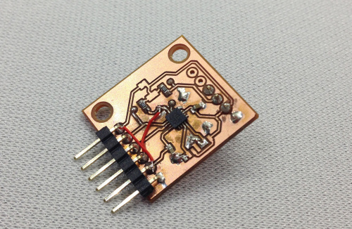
With our first self-milled breakout PCB of the MLX90393 a bust, a second was made. After learning a few lessons from the first, we made a few alterations to the design -- particularly moving a trace out from under the IC and completely removing the center copper pad from under the IC to eliminate potential shorts.
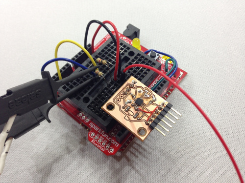
These first two boards were soldered by hand without a stencil, making things slightly more difficult but still achievable. All the solder joints looked good on the second build, and the pins all toned out as they should (or so I thought). The board was handed off for testing. A very primitive test apparatus was made out of a SparkFun RedBoard and a ProtoShield to ping the I2C lines.
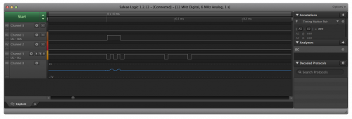
After a few attempts, the initial communication with the MLX90393 was unsuccessful. Out came the Logic Analyzer. We used a Saleae Logic 4 USB Logic Analyzer to troubleshoot the breakout.
After running the analyzer, it was clear that the test jig was attempting to communicate as expected, but there was nothing coming back from the MLX90393.
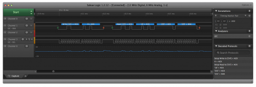
It was back to the hardware drawing board. After a second round of probing with the multimeter, it was discovered that the CS pin, which needs to be pulled HIGH for I2C to be enabled, was actually floating. There was a very tiny chuck of trace that had been disconnected between the 3.3V line and the CS line. The trace was tested for continuity during the first round, but the thru-hole solder joint was not -- a crucial mistake. Luckily, this was a quick fix. The board was attached to the test jig and tested again. This time, we saw the response we were expecting!
We now have our first functioning homebrew prototype!


Nice blog on troubleshooting home brewed PCB. This is the new but interesting topic and also explained thoroughly with images.We also offer services for IPC Training and Solder Certification throughout the US. Anyone can contact us for more info at www.ipctraining.com