Are you afraid to color outside the lines? Do you cringe at the thought of free-handing your way through a project build? Do you experience an unreasonable amount of solace by having all those unruly components locked down to a PCB while you mutter, "Everything in its place, yes, precious"? Well, grab your fave hand tools, 'cuz it's time to step outside your comfort zone. In this episode of ATP, we're going to take a closer look at point-to-point soldering.
Questions? Concerns? Ideas for the next According to Pete? Accidentally soldered your hands together? Leave it all as best you can in the comments, call a doctor, and we'll see you next time!
Interested in learning more foundational topics?
See our Engineering Essentials page for a full list of cornerstone topics surrounding electrical engineering.


Mine's another tube circuit: a musical Jacob's ladder. The output of a big beam power tube drives the primary of an oil burner ignition transformer lashed to V-shaped wires. Plug in a guitar, hit a string, and hear it an a zappy arc. All point-to-point wiring with terminal strips, connectors, and tube sockets.
Building guitar amps, it's not strict p2p wiring that I use for that (though some do).
What I apply is a technique called 'turret-lug' construction. Take a piece of 1/8" Garolite, drill a pattern for the buses and major blocks of the circuit, insert the turret lugs through the holes, swage them on the back of the board, and go to town soldering the topside.
Another tip is to use silver-coated/PTFE-insulated avionics wire. Not because the silver imparts any magical sonic qualities but because it is stiffer. In a high-gain guitar amp, how you route the wires is everything and the stiffness of the silver plated hookup wire really helps.
The PTFE insulation stays nice and intact without shrink-back after resolderings, even many times. Best to get wire strippers that know how to work on PTFE.
Last year I made a series of small sculptures, using the components of functional blinking LED circuits (based on a 555 timer). This one was the largest. I got extra parts to work with by replacing the resistors in the circuit with a bunch of small resistors in series. I mounted the battery and switch on the back side of the board.
Only thing I would add is, pick up the cold soldering iron the same way you pick up the hot one, I swear they look the same.
I built christmas cards a few years ago that had flashing LED's built-in to them as a kind of free-standing tree.
The circuitry for them was a simple flashing circuit built around a 555 timer that I point-to-point soldered and embedded in epoxy in the center of the trees. I unfortunately don't have any pictures of the finished product at hand, but I do have a leftover prototype circuit that I didn't end up using. The final product had the blue wire reversed and replaced with green wire because christmas.
Nice! That's exactly the sort of thing I'm talking about.
I don't know if you'll see this comment over 1 year later, but...
For your exposed HV connections have you considered using something like corona dope (https://www.mgchemicals.com/products/insulating-coatings/red-insulating-varnish-4228) on them once the circuit is finalized? There are various types, but the one I linked to above is a nice pleasing red (very near to SparkFun red).
3kV/mil??? Holy cow! I definitely want some of that!
The Soldering tutorial is simply superb. Thanks.
Thank for the amazing soldering tutorial
Pete, can you do an episode on Contact Resistance? My FlashForge printer died and I found that the connector a 'KEFA' was seriously fried on the ground pin (burnt to a crisp). I managed to get a Molex which was rated for an additional 5A. Talked to my boss and he said that even Molex connectors suck because most are Tin plated. Unfortunately gold plated connector have an 11 week lead time and a minimum quantity in the thousands..... What can I do? What should I do? How to fix? All these and other interesting answer I await thee in a video.
I'm not Pete, but I'll point out that I buy Molex 0008580122 contact pins for that situation. They're gold plated, and Digikey offers them as their part number WM2304-ND and have 5800 in stock for immediate shipment. There's no minimum quantity either: you can buy a single pin for 54 cents, or 50 for $20.28.
(Thanks for answering, Madbodger) Contact resistance. That's a good one, thanks! That and flex circuits. I hate flex circuits.
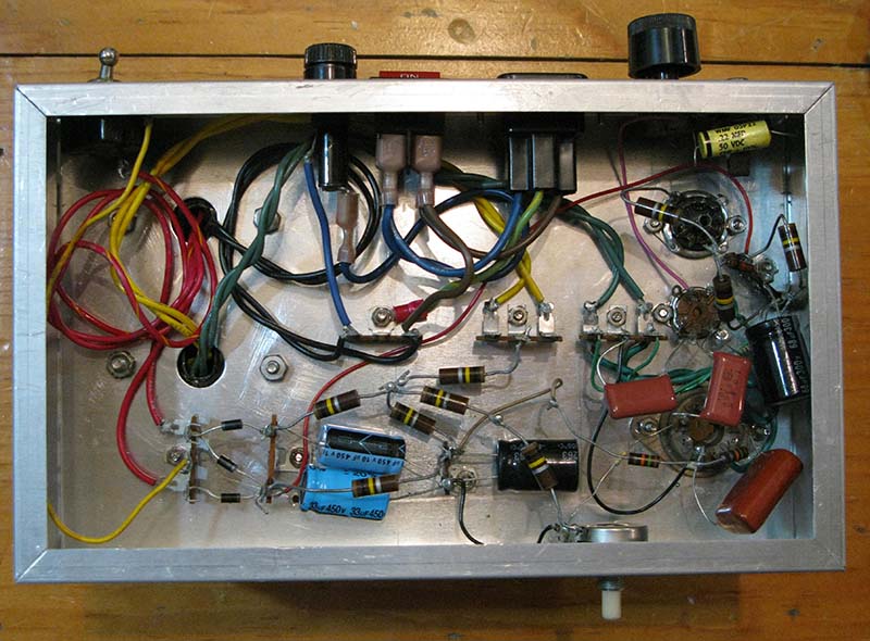
Here's my version of a 1-tube regenerative receiver from Practical Electronics. The original design by Dave Green, W6FFK, was pure 1967 amateur tech with an aluminum Minibox chassis. I substituted the parts I had in my junkbox where necessary and built it on a chassis made from double-sided coppper-clad board (so even the chassis is point-to-point soldering). Anytime I needed to solder to ground it was a simple step to just solder to the chassis.
As you can see, the parts go point-to-point from the tube socket to ground, from the terminal strip to ground and from the tube socket to the terminal strip. The red wire from the power supply is +125VDC, so definitely don't touch the terminal strip until the power supply filter caps are discharged.
My only issue with some of the ptp creations I've seen is the shock/vibe sensitivity. Many of them are way too fragile.
Nice project! It's true, making PTP circuits can be challenging with regard to vibration and safety. Maybe that's why I dig them so much.
My absolute favorite point to point soldering example can be found at: http://www.instructables.com/id/Crystal-cMoy-Free-Form-Headphone-Amplifier/ It's a thing of beauty!
Oh, 'bout four decades ago, I recall piggybacking 2112 RAM chips and soldering pin-to-pin on my KIM-1 to double the memory to a whopping 2 KB. I used an early generation battery-powered solding iron, a Weller I think. My girlfriend had to hold the the piggybacked chips steady until I soldered a pin or two.
Recall, also, that all consumer electronics was soldered point-to-point before the advent of printed circuit boards around 1960 or so. My first shortwave radio, a Hallicrafters S-38E was point-to-point. Inside, it looked like a semi-organized rat's nest, and gave the sense of mass-produced DIY. Ah, nostalgia just ain't like it used to be.
Pete! You should have mentioned dead-bug construction while you had an example open on your bench!
Also, a series on “Circuit Building Techniques That Time Forgot!” would be good, including Dead-Bug, Cordwood Construction, and Wire Wrap.
That's an interesting idea. I honestly can't abide wire wrapping, and can't figure out why people still do it. Just solder the wires! I wouldn't say that dead-bugging is a forgotten thing, though. Hey, sometimes you gotta prove a circuit before you have a PCB. But I'll normally do that on a perf board or some other PCB just to get a workable hard point.
Those are reasonable answers, and I can certainly get on the zen-bus about the sort of satisfaction I get from doing this sort of work with my hands. And there are those that would argue that soldering is going a similar way as wire wrap, that it's unnecessary (or less necessary) in the larger scope, that everything is going towards a plug-n-play sort of thing, that you can just plug in a few sensors to your pi, work up a new phone app for it and hit San Jose to get bought up by Google. But I'm not one of those. I'll always be a hardware guy, so I know exactly where you're coming from.
Oh the days of debuging a 3000+ wirewrap backplane.