If you've ever had to build a power supply, you may have needed to test it to a certain current limit. Too often, the way to do this is by stacking up large wattage resistors in series and parallel until you've got something that approximates the load you want.
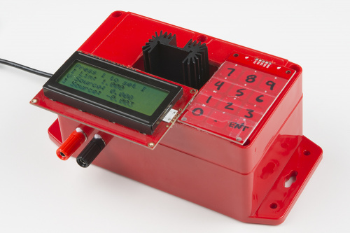
I got tired of doing this, and whipped up this little tool to help me test my power supplies with a little more aplomb.
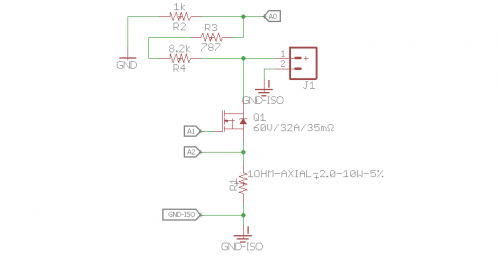
I'm a big fan of the Cypress PSoC line of processors, which is on our FreeSoC2 Development Board, so I decided I'd use a FreeSoC2 to implement my load. The PSoC has a huge advantage over other systems in that it has a lot of onboard analog circuitry (four op-amps), true 8-bit DAC outputs (instead of PWM), a high-accuracy 16-bit differential sigma-delta ADC and a couple of channels of SAR ADC. With all of this onboard power, I was able to reduce the external circuitry down to a few resistors and a FET as a load element.
You can see here the 10:1 attenuator for the input voltage sense, which allows us to test power supplies up to 50V. The FET is going to be operated in the ohmic region, where it behaves like a voltage-controlled resistor rather than a constant resistance switch as we usually use it.
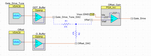
This is the internal circuitry created within the PSoC. Two DAC channels provide a coarse (16mV/count) and fine (4mV/count) adjustment for the gate drive voltage. These signals are brought out of the PSoC, run through a couple of 47k resistors, and then pushed back through an inverting amplifier with a gain of 1 to create a summing amplifier for driving the FET gate.
For user I/O, we're using a 20x4 character LCD, along with one of our MPR121-based cap sense keypads. The FreeSoC2 has a dual-voltage domain setup that allows us to run some pins at 5V and others at 3.3V, so you don't have to worry about level shifting the 3.3V signals for the MPR121.
Finally, the code is written in C under PSoC Creator 4.0. The PSoC on the FreeSoC2 is clocked (for this application) at 64MHz, which is fast enough to do the PID loop, floating point math and all, at 1kHz, despite the lack of an FPU on the processor.
All the code, schematics and such are uploaded to this GitHub repository. I don't recommend trying to make the board I made just yet; I neglected to add the 47k resistors and a connector for the cap sense keyboard. I'm going to respin the board and add these things.
If you do try out a similar project, or if you have any thoughts on this, let us know in the comments below!


I have a quick request. Once you have the schematic and board finalized, please provide both the schematic and a board output as pdf files in the GitHub repository so they can be viewed on machines that don't have Eagle installed (and can't have Eagle installed because they are controlled by corporate IT). I don't know if it is necessary to have board fabrication plots in the PDF, but an overview representation much like what one sees on screen (dimensions on important features would be nice) when designing. Or if you have the appropriate 3D models, a 3D rendering of the board would be nice.
If you are going to sink any appreciable amount of current, the FET is going to get very HOT. Perhaps a better solution would be running the FET in a PWM mode with an inductor to smooth out the current ripples.
A load for testing power supplies is going to get hot somewhere—it's function is to dissipate a controlled amount of power. The linear solution here makes more sense than a switched solution, because a lot of power-supply testing is looking at how much ripple it produces and introducing more ripple from the adjustable load would hide that. Also, one might want to look at the power-supply response to step increases in current, which an inductive load is not capable of emulating.
That said, I don't see the attractiveness of the PSoC line of microcontrollers here—the analog circuitry is just being used to compensate for the inadequate resolution of the DAC and ADC. A KL26, such as in the Teensy LC board, would be a simpler solution.