When I started at SparkFun, they showed me the laser cutter and told me it was available once I was trained and tested. I searched for laser projects online and found this pseudo nixie tube. With a little modification, I had a plan for a clock.
Basic Operation
Edge Lit Display
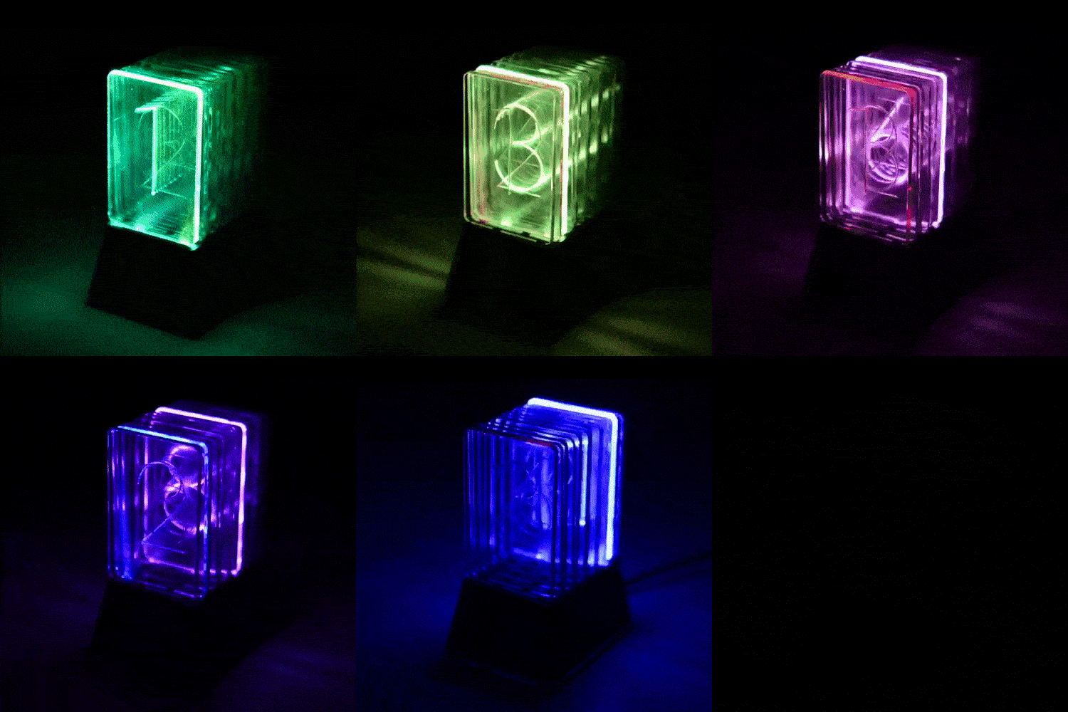
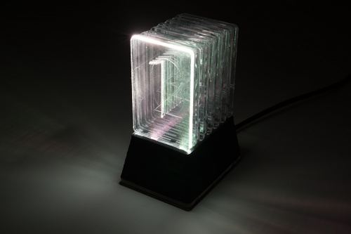
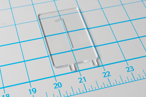
This type of display is commonly called "edge lit." It works by transmitting light from the edge of a clear material to the next available imperfection or edge in that material. The numbers are cut part way through the material thickness to create the surface imperfection in the shape of a number. Since it is only part way through the tile, light can still pass by to reach other parts of the number. One shortcoming of this display type is performance in ambient light. This clock will live the rest of its life in near dark.
Time Display
Only one tile lights up at a time. The number on that tile indicates the current hour on a 12-hour clock. While I prefer 24-hour time, 24 tiles would be a little absurd, and doubling up on the numbers would be difficult to read.
The color of the tile indicates the minute. I chose a gradual fade from color to color, so it's not going to remind you of a meeting, but you'll get the gist of how far we've traveled though that hour.
Construction
Tiles
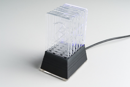
Using 1/8" clear acrylic, I cut the nixie tiles with the laser -- 1-12 to represent hours. The teeth on the bottom double as support for the finished clock and a path for light to travel from the LED to the etched number.
Base
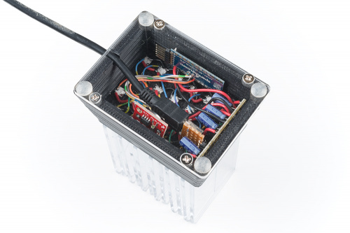
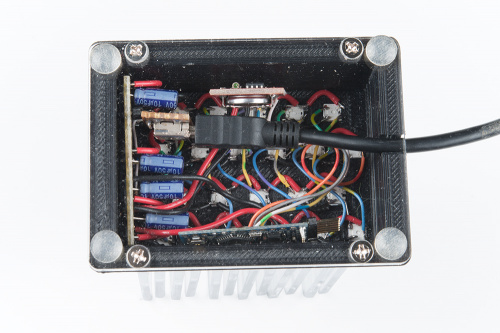
Instead of using the base from the original project, I redesigned it for 3D printing using Fusion 360. I wanted a larger cavity for the electronics I chose.
Electronics
LEDs
I chose Surface Mount WS2812s because I wanted addressability with minimal wires. I started marking the PCB side with their orientation. They do not come from the manufacturer with any such indication; in the photos you can see a black dot toward the power cord side of the base. I stripped and soldered all the wires by hand. That's not very fun on SMD components.
The datasheet for this component calls for a capacitor at each LED. I scoffed at the idea of freehand soldering another 24 SMD components and added large capacitors at the beginning of each row. Somehow I got lucky and it works. Please don't scoff at your datasheets; it's a bad habit and I should stop doing that.
Real Time Clock
The SparkFun Real Time Clock Module keeps time. Since it also tracks the date, I plan to make the firmware update for Daylight Savings Time (whenever I get around to that).
Controller
The brain of this clock is an Arduino Pro Mini 5V. Since the LEDs run at 5V also, and I had one of these laying around, this one was a good choice for me. If I do it again, I'd prefer a different board that is programmable over USB, instead of requiring a FTDI cable.
Power
My ever-increasing pile of cables at home is someday destined for the e-waste bin, but I try to use them whenever possible for hookup wire and whatnot. This project makes permanent use of a USB cable for power input. I salvaged a USB connector from an old broken circuit. This connector worked well enough with proto board, so that's how I connected it.
Lessons Learned
Not everything turned out like I planned, so here are some tips if you try to make one of these for yourself.
Cover the Acrylic
While laser cutting, leave the protective covering on. Getting smoke off of the clear surface is difficult in some areas and impossible in others.
Make the PCB
A circuit board for surface-mount components would have been so much easier to solder. It also would motivate me to put on all the capacitors like the datasheet recommended.
Alternately: Use Through-Hole LEDs
The other option for making this easier is to use our WS2812s with legs. Those would save so much wire stripping! I could probably figure out a way to get capacitors to each LED with that much leg.
Code for Daylight Savings Time
Currently I have to change the hour twice a year. I should have made that part of my original goals in code. Instead I decided to put it off until later. In other words, I'll just update the time twice a year indefinitely, because I'll find other higher priority things to work on.
1/8" Acrylic is thick
In a second go-around, I'd use thinner material. That would probably mean a different layout of LEDs and the legs of the tiles -- lots of work there. Getting the layers into a shallower depth would increase the view angle of the display.
Open Source
I made this open source, so if you'd like to make (and improve) your own, here's the source.
Interested in learning more about LEDs?
See our LED page for everything you need to know to start using these components in your project.


I have accumulated so much electronics gear and help run a fledgling MakerSpace, but I never find any projects that I dedicate the time to building. Our makerspace has 3D printers and a 150W laser cutter, and I've been trying to find a project that uses them both. I'm committed - I will be building something using this project as my inspiration!
I would use an ESP8266-based board so the clock syncs to Internet time servers over WiFi. Then you could use this library to automatically handle Daylight Saving time: https://github.com/JChristensen/Timezone
Techmoan made a video on a German-made LED nixie clock. Here is his video: https://www.youtube.com/watch?v=miqN2gR1Zns
I built the Ice Cube clock, and took the project one step further by encasing the display tube in clear casting. Here's the project on Instructables.com: http://www.instructables.com/id/Ice-Cube-Clock-3/
The Russian display tube used in the Ice Cube Clock is no longer available and I'm wondering if the Nixie LED Clock display would have a good presentation encased in casting.
Pretty cool!
Edge lit laser cut acrylic for the win! I used a similar approach for this Doctor Strange prop.
That looks really good. Do you have lights completely surrounding the edge?