As many fledgling makers, tinkerers and hobbyists do, I became deeply imprinted on addressable LEDs. I mean, even making just one light up feels like your own personal disco party, so what's not to love about 100... 500... 1000+? Between the exponential growth of the number of LEDs in my projects and a small dose of perfectionism, I became concerned with the most efficient ways to update LED data. This is the story of how a hardware fix was required to work around the Arduino IDE in pursuit of maximum speed.
Basics of LEDs and Speed
After abandoning any pretense of "real world applications" and just admitting that we are obsessed with maximum performance, let's decide how we can stream out LED data the fastest. This problem starts with the choice of LED strip. There are two predominant types of LED strips - those with two-wire control, like the APA102, and those with one-wire control, like the WS2812B. One-wire control only uses one data line and relies on the master (your Arduino) and the slave (in this case the LEDs) to agree on a data frequency. Two-wire control, on the other hand, uses a clock line to tell the LED exactly when the incoming data is valid. This allows much faster and more flexible communication to occur. Here's a brief overview of the similarities and differences:
| Two Wire (APA102) | One Wire (WS2812B) | |
|---|---|---|
| Color Depth (bits) | 24 | 24 |
| Brightness | Stunning | Dazzling |
| Communication | Synchronous | Asynchronous |
| Minimum bitrate | 0 Hz | 800 kHz |
| Maximum bitrate | 10 MHz+ | 800 kHz |
| Theoretical max LEDs at 60 Hz | 5208 | 417 |
In a lot of ways, these two technologies are comparable - they're both very beautiful to look at. However, for high speed applications the two-wire control method is superior. Next we need to consider how to actually send data out of the master as quickly as possible.
Perhaps the most obvious way to send out the data is to 'bit-bang' or toggle the pins manually. This method can be executed pretty quickly by using assembly instructions and directly accessing pin control registers, but as we learned in Go Speed Racer...Arduino Speed Test, using the Arduino digitalWrite() function has a lot of overhead. Don't fret, most micros come with an easier and more reliable method.
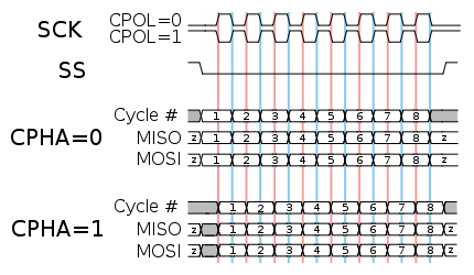
The SPI peripheral built into microcontrollers can often output data at nearly the speed of the CPU clock, and can be configured to any combination of clock polarity and data phase - this is called the SPI Mode. By checking the APA102 Datasheet we can see that SPI_MODE3(CPHA = 1, CPOL = 1) is a perfect match. Okay, now we've figured out how to best send out data from the microcontroller. The next step is to make sure that data is what we want it to be, so we need a way to specify the LED pixel info. This will bring us to discuss the problem I discovered in the Arduino environment.
The Problem with Arduino
We're prepared to send data out as fast as we can, but we definitely have some strong opinions on what that data should be. Although there are a lot of unique ways you can specify and store that data, the simplest way to think of it is an array of bytes in memory. I even tend to have a mental image of them being laid out along the length of my LED strip! To control the LEDs we will need to send out each byte in that array in order.
At the lowest level, everything in a microcontroller is configured, controlled and evaluated by writing data to specific places in memory called "registers." The beauty of an IDE is that it provides an interface to those registers that is far more intuitive and easier to use. The Arduino environment has a built-in library to support the SPI peripherals on whatever board you are using. The function SPI.transfer() is the Arduino-provided method to send (and receive) data on the SPI peripheral.
In the Arduino Reference you can find that SPI.transfer() has two ways to send out byte-sized data. The first is a single byte write, and the second will write every byte in an array of length "size" called "buffer."
My intuition told me that making only one function call would be more efficient, but I soon discovered an irritating problem: When using the buffer-write version, the data in your buffer will be overwritten by whatever was on the MISO line when the data was clocked out. This is intentional, of course, but it obliterates the LED data that you had just so carefully set up to display an image of a cat! Here's the code deep down inside Arduino:
inline static void transfer(void *buf, size_t count) {
    if (count == 0) return;
    uint8_t *p = (uint8_t *)buf;
    SPDR = *p;
    while (--count > 0) {
        uint8_t out = *(p + 1);
        while (!(SPSR & _BV(SPIF))) ;
        uint8_t in = SPDR;
        SPDR = out;
        *p++ = in;
        }
    while (!(SPSR & _BV(SPIF))) ;
    *p = SPDR;
}
The offending snippets are (in combination) uint8_t in = SPDR; and *p++ = in;. The first takes the value out of the SPSR register and is required because of the way that the SPI peripheral works. The second snippet overwrites your buffer values (how dare they?).
Having identified the cause of the overwrite you might see an obvious solution: Comment out *p++ = in; so that your data is not overwritten, or define new functions called transferOUT() and transferIN() that work the way you like. This is a totally viable way to get your project working, but it is not acceptable for development of Arduino libraries.
When developing libraries (like the RGB OLED 64x64 library), it is important to keep the "guts" of Arduino vanilla so your software can be easily used by others. Another solution could be to join the Arduino developer's email list and propose a change, but this is a process that requires a lot of consideration and agreement between other parties. Instead I needed a fast solution.
Cost of the Problem
Do as I say, not as I do. Even though I rushed into making a solution it is usually good practice to make sure that the problem really is, well, problematic. I got lucky and found a justifiable benefit in the solution after the fact. Here I will pretend that I did this in the right order!
What are possible solutions to the problem?
- Fill out a buffer every time before sending it (my usual solution, but feels icky).
- Use
SPI.transfer()one byte at a time because it preserves the value of that byte. - Develop a hardware solution that saves the contents of the buffer automatically.
1
for(uint16_t indi = 0; indi < NUM_BYTES; indi++){
    buffer[indi] = value;
}
SPI.transfer(unprotectedBuffer, NUM_BYTES);
2
for(uint16_t indi = 0; indi < NUM_BYTES; indi++){
    SPI.tansfer(unprotectedBuffer[indi]);
}
3
SPI.transfer(protectedBuffer, NUM_BYTES);
We can define the cost of the problem as the difference between existing solutions and the most ideal solution. If the cost of the problem is large enough, then it is worthwhile to develop the ideal solution. In this case the ideal solution is the ability to use the SPI.transfer() function on a buffer without having to re-enforce each data value every time. I created an Arduino benchmarking sketch that tests the time it takes for these three methods to complete for a given number of bytes to transfer.
I tried using a Desmos graphing calculator to visualize the results, but for any significant number of LEDs (greater than about 10) the results become very linear and it just makes more sense to show you a table of the data rate in terms of microseconds per byte transmitted:
| Arduino UNO | Arduino UNO | Teensy3.6 | Teensy3.6 | |
|---|---|---|---|---|
| (us/byte) | (LEDs/60Hz frame) | (us/byte) | (LEDs/60Hz frame) | |
| 1, Pre-enforce | 2.724 | 1529 | 1.022 | 4076 |
| 2, Individual writes | 2.984 | 1396 | 0.843 | 4940 |
| 3, Buffer Saver | 1.400 | 2976 | 0.808 | 5154 |
I found it interesting that the rank of methods one and two switched between the two platforms, but that is a topic for another article. In the case of both the UNO and the Teensy we see that the third method is faster - nearly twice as fast as the pre-enforcement method on the UNO.
The Solution
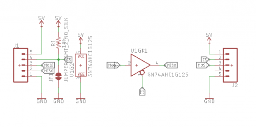
Having totally proven that this would be a worthwhile use of time beforehand it was time to come up with a solution. The way this came to me was a lot like pure inspiration. Basically I thought, "The data I need is coming out on pin 11, and needs to go into pin 12... can we just hook them together?" I quickly proved that it would work with a jumper wire (ignoring any analysis of SPI modes and phases etc...) and then was off to the races. My main concern was that simply connecting MOSI to MISO would prevent that SPI bus from being used for other sensors. This told me that we needed a way to electrically decide if the two lines would be connected. A tri-state buffer with an active-low enable pin is the exact right piece of gear to do so. Here's how it looks in the schematic:
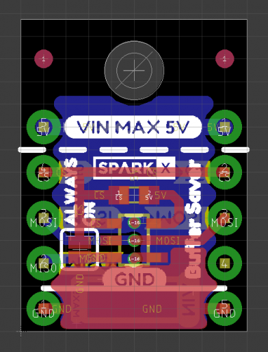
Some other design features I included were the ability to force the enable pin low with a jumper, and allow for an extremely compact footprint by chopping off the part above the dashed line by placing a 5V passthrough pad on the back of the board. These features make the BufferSaver perfect to fit right in-line with the data and power lines going to an LED strip or one-way, SPI-controlled display.
Verification
With a solution determined the final step was to validate the solution. I needed to make sure of two things:
- That high-speed (10 MHz) signals could pass through the buffer unchanged
- That MOSI data did not affect MISO when the buffer was disabled
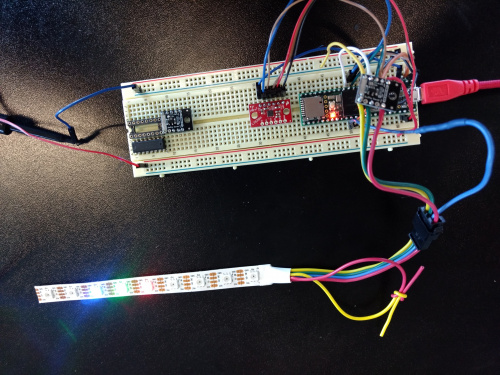
The testing sketch I wrote demonstrates that the Buffer Saver does what it was designed to do by placing an APA102 LED strip on the same SPI bus as an LIS3DH accelerometer. The Buffer Saver protects the LED data instead of having to re-write it all each time, but still allows the accelerometer to control the MISO line to send data back to the microcontroller.
This is the Buffer Saver in action! While testing everything out I realized that it was really odd to have sensors connected to the same lines as an LED strip and it got me thinking. On the next verison of the Buffer Saver there will be a second tri-state buffer that disconnects the LED strip from the MOSI line when not selected. This will allow you to control multiple unique LED strips with just one SPI port!
I've also provided a DLA capture that shows the input and output signals when driving the LEDs at 5 MHz. If you'd like to inspect the capture more closely you can download it below and open it with Saleae Logic.
Now I am curious to know if anyone else thought of another solution to the SPI.transfer() problem? Do you think you could find a use for two different LED strips on one SPI port?


No hard feelings, but this seems like a lot of effort to work around a single line of code. As the article shows, Arduino's library contains a single line that writes back into the provided buffer. It was a bad design on Arduino's part, but I suspect they are stuck with that API/functionality across the product line now.
To give us some flexibility, I'd write a new SPI transfer function. This is untested, but here's my idea.
This would allow for either full duplex (both directions) or half-duplex (one direction) communication, by simply setting one of the pointers to NULL (or "nullptr" in C++).
You're correct about Arduino being stuck with it and this is an excellent solution in most cases! The situation where a hardware solution might begin to be attractive is when you are trying to max out the effective data rate - either to boost the update rate (framerate) or trying to increase the total number of LEDs while still hitting a target update rate. Your solution is also reminiscent of the extended SPI functions that we were able to include in the Apollo3 Arduino core - transferOut and transferIn (just one benefit of maintaining your own core!)