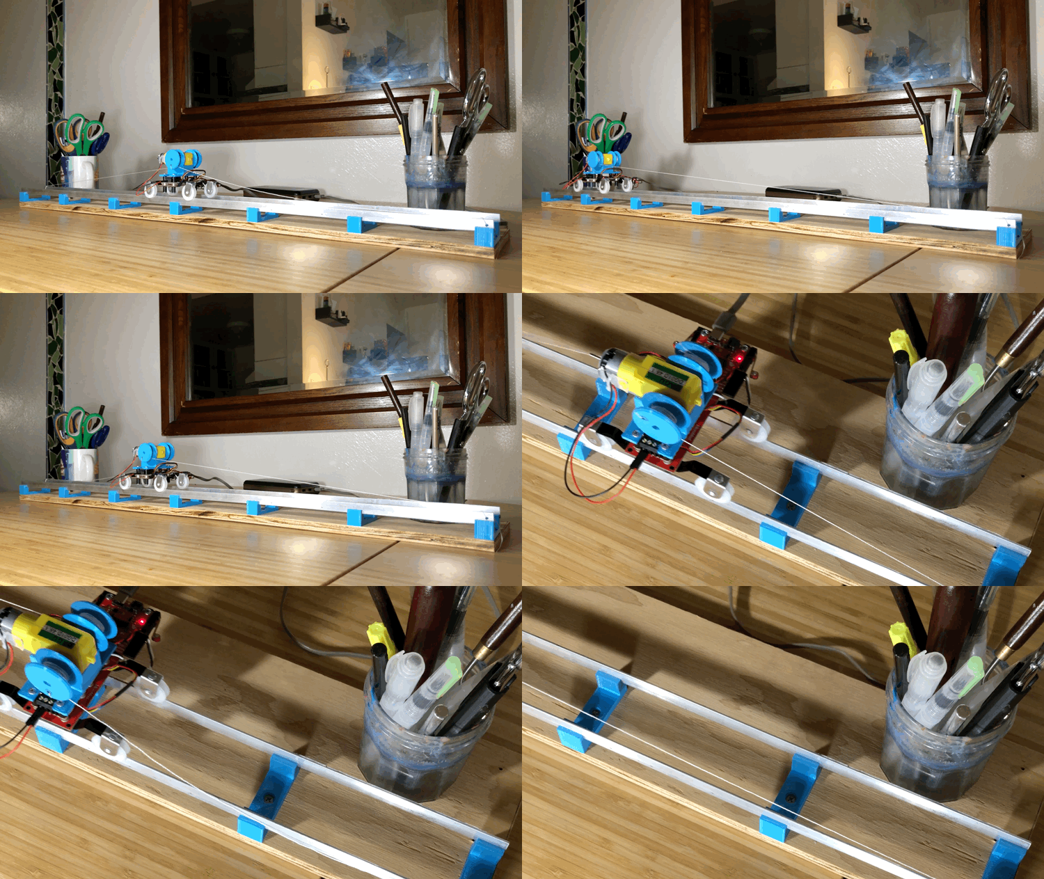
MicroMod Rail Car in Motion
Lately I've been experimenting with different DIY solutions for linear motion so that I can design and build my own custom plotters and CNC machines. This simple project encapsulates the basic elements of a linear motion system. Using the MicroMod Qwiic Carrier Board as a chassis, this linear motion system could be adapted for any number of applications, or you could even just build it for fun.
From the hardware store:
- 1/16" thick, 1/2"x36" Aluminum Flat Bar (X2 - for rails)
- Screen Door Tension Spring with Roller, Academy 2-pack (X2)
- String
- small wood screws (for mounting rail holders, optional)
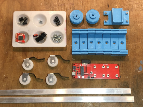
MicroMod Rail Car Parts
How to assemble the MicroMod Rail Car:
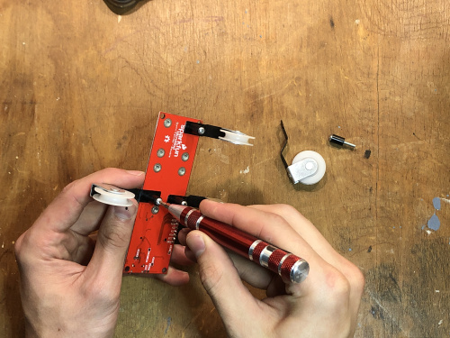
Thread four ¾” 4-40 screws through four nylon standoffs as shown in the top left corner of the above image
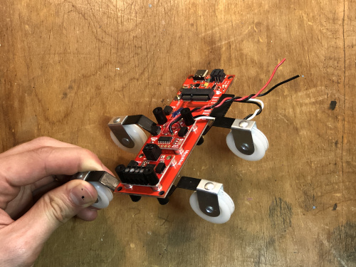
Use these four standoff screws to secure the four spring rollers to the underside of the Qwiic carrier board as shown below.
Roller Assembly
Place the Qwiic motor driver on the mounting posts furthest from the carrier’s USB connector, using two nylon standoffs to secure it in place. Make sure the board is oriented so the 4-pin screw terminal is on the “outside” and can be accessed later.
Connect the 2-pin screw terminal on the motor driver to the ground and 3.3V pins of the carrier board with some jumper wire. I soldered a right angle header to mine to make this easier.
Motor Driver Mount
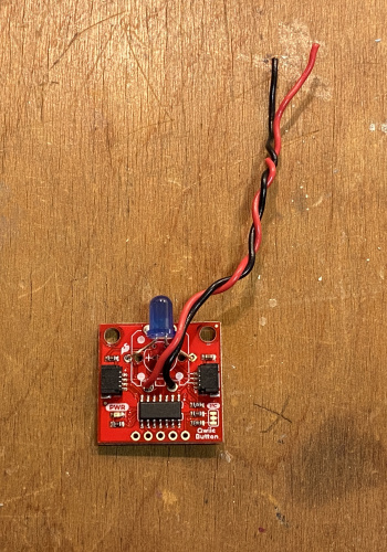
- Solder some jumper wire to the pin holes on the Qwiic button board (as shown). I also soldered a blue LED to the LED pins, but this example doesn’t utilize the LED so this isn’t totally necessary.
Qwiic Button Breakout Wireup
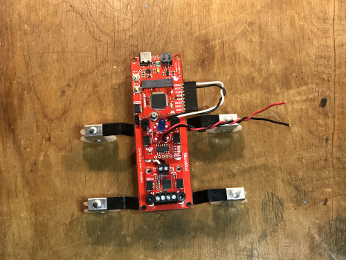
- Secure the Qwiic button breakout to the second set of mounting posts using two nylon standoffs.
Mounted Qwiic Button Breakout
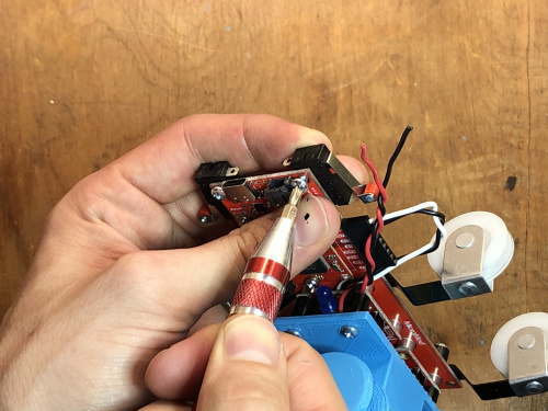
- Insert the SAMD51 processor into the M.2 connector and secure it in place with the included screw.
Mounting the SAMD51 Processor
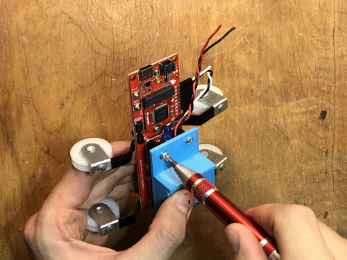
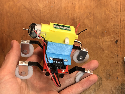
- Secure the 3D printed hobby motor mount to the nylon standoffs using four ¼” 4-40 screws. Secure the hobby motor to the mount using double-sided tape, and insert the motor wires into the screw terminal as shown.
Securing the Motor Mount
Attaching the Motor
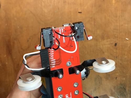
- Using two ¼” 4-40 screws, mount the microswitches to the carrier board’s mounting holes as shown. The mounting holes on my microswitches were slightly smaller than the screws, so the friction was enough to hold everything in place.
Mounting the Limit Switches
- Solder the “contact” (C) and “normally open” (NO) pins of the switches together using some jumper wires, and then connect the jumper wires from the qwiic Button board as shown.
Limit Switch Wireup
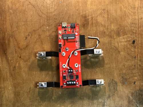
Finally, complete the circuit by connecting the qwiic breakouts to the carrier using some 100mm Qwiic cables.
As long as you’ve already completed the setup for the SAMD51 MicroMod processor, you should be able to upload the following sketch to test out the Qwiic rail car. If everything is working, after you upload the sketch, click one of the limit switches and the motor should start turning. If you click the limit switch again, the motor should change directions.
MicroMod Rail Car Sketch:
#include <Arduino.h>
#include <stdint.h>
#include "SCMD.h"
#include "SCMD_config.h" //Contains #defines for common SCMD register names and values
#include "Wire.h"
#include <SparkFun_Qwiic_Button.h>

QwiicButton button;
uint8_t brightness = 70;

SCMD myMotorDriver;

#define LEFT_ 0
#define RIGHT_ 1
#define LEFT_MOTOR 0
#define RIGHT_MOTOR 1

void setup() {
  // put your setup code here, to run once:
  Wire.begin();
  button.begin();
  button.LEDoff();

  pinMode(8, INPUT_PULLUP);
  myMotorDriver.settings.commInterface = I2C_MODE;
  myMotorDriver.settings.I2CAddress = 0x5D;
  myMotorDriver.begin();

  while ( myMotorDriver.busy() );
  myMotorDriver.enable();
  myMotorDriver.setDrive( LEFT_MOTOR, 0, 0);
  myMotorDriver.setDrive( RIGHT_MOTOR, 0, 0);
}

bool directionMoving = false;

void loop() {
  bool limitReached = false;
  limitReached = button.isPressed();
  if (limitReached == true){
    if(directionMoving == true){
      myMotorDriver.setDrive( LEFT_MOTOR, 0, 100);
      directionMoving = false;
    }else{
      myMotorDriver.setDrive( LEFT_MOTOR, 1, 100);
      directionMoving = true;
    }
  }
  delay(200);
}
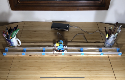
- To assemble the full linear motion system, simply snap the 3D printed rail holders onto the aluminum bars and (optionally) screw it onto a piece of wood using the mounting holes of the rail holders.
Fully Assembled Linear Motion System
- Wind some string onto both spools, making sure each spool’s length of string is longer than the length of the rail. Snap both spools onto either side of the hobby motor, and place the assembled rail car onto the assembled rails as shown. Drill two holes, one at either end of the rail, and unwind some string from either spool to attach the rail car to the rail (as shown). Now, when you power up the MicroMod Qwiic Carrier Board and tap one of the limit switches, the motor should pull the cart along the rail from one end to the other. You can make the cart ping-pong back and forth by placing objects in the path of the limit switches.
