TL;DR: We did some testing to develop our own best practices for designing PCB breakaway tabs and published an industry white paper about it. You can download the white paper here or read on to hear about our test methods!
Mouse bites, rat bites, perforated breakaway tabs, whatever you call them -- they're an indispensable part of every board designer's bag of tricks. What's that? You've never heard of them? Well, that changes today!
"What's a Mouse Bite?"
When you just need to build up a few boards you probably order the PCBs as individual pieces and assemble them one at a time. However, if you're building a SparkFun amount of boards you need every efficiency you can get. So when we build a big batch of Qwiic Blower Fans, for instance, we combine them into larger boards called panels. These panels go through the entire assembly process together, allowing us to save time handling boards and moving them between machines. At the end of the process, the panels are separated back into individual boards! Usually, the boards that make up a panel are connected by what's called a "v-groove" (sometimes called a "v-cut" or "v-score") which is basically what it sounds like: A v-shaped groove is sawn into both sides of the board which makes it easy to snap apart.
Sometimes you can't use v-grooves, though. Because of the way they're cut, v-grooves have to be perfectly straight and must extend the entire length of a panel. This is basically a non-starter for round boards, like the LilyPad ecosystem. It also causes problems for boards that have straight edges but might have connectors that overhang the board edge. So how do we combine oddly-shaped or overhanging boards into panels that we can still snap apart after assembly? Breakaway tabs!
Breakaway tabs are small bridges of PCB that are designed to break away from the finished design. They break because of a row of closely-spaced holes at either end, which act like the perforations on the edges of a postage stamp. These rows of holes got the nickname "mouse bites" because the indentations left behind after they break look like the tooth marks of some tiny animal who took a chomp out of the board. Sometimes they're even used as part of a kit design, like the LilyPad ProtoSnap Plus, which tucks signal traces in-between the mouse bites to allow the user to develop their application before snapping the parts out and sewing them into a project.
"Does anyone know [...] how to do mouse bites correctly?"
The thing about mouse bites is that they're hard to get right. Sometimes they're too fragile, more often they're too sturdy; sometimes they leave a mess, sometimes a circuit fab just refuses to make them as designed. So when Nate was faced with adding mouse bites to a design recently, he sent an email to the rest of the engineers asking for advice. Everyone had their own rule-of-thumb but there wasn't any documentation. We didn't have an established "best practices" for mouse bites. Personally, I have a reputation for borderline abusing mouse bites in my designs outside of SparkFun, so Nate asked me if I knew of a document to point to outlining the ideal mouse bite... of course I didn't. I had a rule-of-thumb like everyone else (20 mil holes, 40 mils center-to-center) but I only did it that way because it seemed right and it was easy to remember. And so I was sent on a quest to find some kind of authority on mouse bites.
A survey of circuit fabricators’ websites suggests that the industry has landed on the following figures: unplated holes with a diameter of 0.020” which are spaced 0.030” apart. Browsing the forums suggests that this is a common convention. Some people suggest larger or smaller spacing, some suggest larger or smaller holes, but all within a few thousandths of an inch. The trade association IPC offers some guidance in their publication IPC-7351, or “Generic Requirements for Surface Mount Design and Land Pattern Standard,” a 100+ page document which spares a few sentences in chapter 3.4.8.3 to describe break-away tabs. The accompanying figure suggests that typical dimensions are actually 0.031” in diameter and spaced 0.050” apart.
Faced with all of these slightly differing figures, I did what any reasonable person would do: took the average, pointed Nate towards a blog post on one of our circuit fabs' websites, and called it a day.
Just kidding, I ordered $400 worth of PCBs on the company card and snapped them all in half one at a time!
The Scientific Method
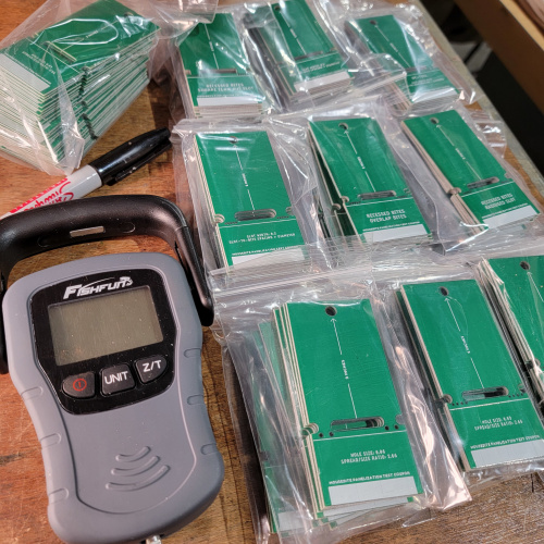
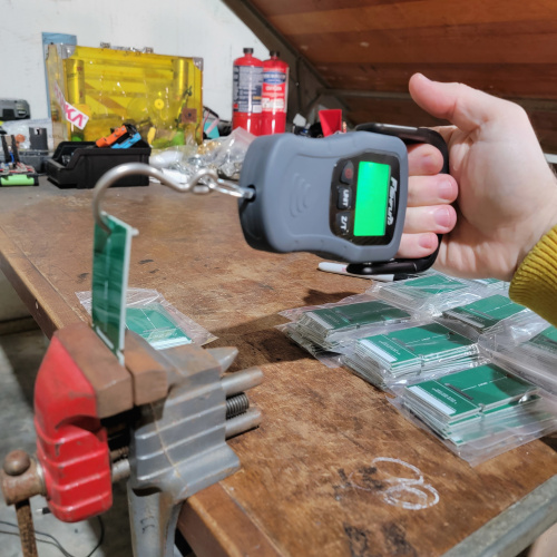
Mouse bites are pretty simple, so there are only so many things that can change to make them better or worse. This is good news for us because it means that we have relatively few variables to control for. I settled on four different parameters: hole diameter, hole spacing, edge clearance, and tab corner radius. For each of these parameters, I prepared a series of test coupons which are just small PCBs with a mouse bite in the center. Each test coupon was flexed to breaking in a controlled manner and the force required to break it was recorded in a spreadsheet. The breaking force was measured using an inexpensive fishing scale. This scale was chosen because it's sensitive within about 20 grams and it also has a peak hold mode which could be used to measure the maximum force applied before breaking. The test coupons were mounted in a bench vise using a silkscreen line on the boards themselves to ensure they were held consistently between trials. Five trials were performed for each variable.
Test subjects lined up next to the Fishfun scale (no relation)
My highly-scientific strength testing machine, calibrated and ready
After all of the test coupons were processed, they were lined up for photos. The breaking strength is only one of two major factors that determine a mouse bite's success, the other (as is too often the case) is looks. It doesn't matter how Goldilocks the breaking strength is if it leaves behind a jagged, ugly, dangerous edge. So I ended up with a folder full of photos that looked like this:
"Do you see the suspect in this lineup?"
"What did we learn, Palmer?"
These tests did actually produce compelling data that ultimately steered us toward a recommendation! We now have a set of guidelines for designing breakaway tabs, which we'll use on all of our designs going forward. Or at least they'll provide a starting point for all designs going forward, because the truth is that the best breakaway tabs are the ones that make life easiest for your manufacturers and assemblers, and that might change slightly with the demands of a given design. Our recommendations are a solid starting point, though, and I think they'll work for most projects without alteration.
If you want to find out what those recommendations are, you can check out the PDF white paper. It's licensed under a CC-BY-SA 4.0 License, so feel free to share it, remix it, and publish it yourself. Pro Tip: Page 9 outlines the mouse bite pattern I settled on.
What other minutiae should I be obsessing over for the good of the community? Let me know in the comments, I love to play scientist. Next time I'm buying a lab coat.


Sweet! This was an interesting and enjoyable read. =)
Cool!
Nick,
It's a very interesting paper. Thanks for sharing it, and thanks, too, to Nate for supporting the research!
I'd like to mention one of my "hot-buttons" on a slightly related topic: When you're doing surface mounted devices that will be subject to mechanical stress, such as Qwiic connectors, put some "micro-vias" to a pad on the other side of the board, and make sure that they DON'T get solder masked. This can greatly enhance the "adhesion" of the mounting pads, there by greatly reducing the chance of accidentally ripping the connector off the board. (Of course, using connectors that at least have "through hole" mounting pins is even better -- for instance, micro USB connectors can be had either with through-hole mounting tabs or as "purely" SMD connectors -- I only use the former in my designs. Unfortunately, Qwiic connectors are only available as "purely" SMD.)
Thanks!
That's an interesting point about the Qwiic connectors. I, too, am annoyed by SMD connectors because they have that problem. The SMD-only Micro-B was the worst offender I can remember. Micro-via stitching is a great idea. I've used it on my own boards in the past (I think I even mentioned it in my 2020 Supercon presentation on PCB construction techniques!)
Have you had problems with the Qwiic connectors coming off? I haven't run into it yet, but I can see how it would happen. If it's a genuine problem, I can start a conversation on our side about adding vias and anchor pads to the connector footprint.
Thanks for the feedback, as always
I haven't had any problems so far, but at the moment I've been pretty careful with them.
I put a provision for a Qwiic connector onto it, and did include the micro-via stitching for the side "ground" connectors, which give the primary mechanical strength. I'm sure I don't have to tell you that the "pin outs" for the horizontal and vertical versions of the socket are "reversed" if you try to put the solder pins on the same side. I had to do a rev of the board for other reasons after I discovered this, and did a modified footprint for the Qwiic connector so I can decide whether to use the vertical or horizontal connector when I'm actually building up the board.
Had I been able to get Qwiic connectors with through-hole mechanical connections, I certainly would have used them from the get-go.
And thanks again for the nice write up!