Today (October 22nd, 2011) is the SparkFun Open House! We are expecting a lot of people and it is sure to be a good time. We're going to have a whole gaggle of fun stuff - like bouncy castles, free food, tours, workshops, swag, and more - so swing by the SparkFun headquarters today from 11 am - 4 pm. We hope to see you here!
This week we have something special for you. Instead of the usual shenanigans in the product video, I decided to do some something a bit more educational. People are always asking for more tear-downs, more in-depth explanations of products, etc. So this week I decided to explain stepper motors and servos. Granted, it's general information and of course there are caveats and such, but it should serve as some good fundamental knowledge.
So there you have it, the longest video I've ever done here at SparkFun. I hope it helped out some of you. And if you like it, I hope to do more like it in the future. It's always fun taking things apart!
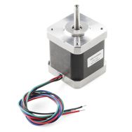
So, we have some new stepper motors this week. In addition to the small stepper motor we started carrying a few weeks back, and the other one we've been carrying for several years, we have this 58 oz.in stepper. It has a full 400 steps per revolution so you should be able to get some good accuracy for your next project.
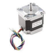
Need a little bit more oomph? This 125 oz.in stepper motor is pretty hefty and should work when you need the extra torque. They're really well made and have a 0.25" output shaft for easy mounting.
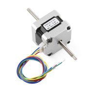
If you are looking for a linear motor, why not check out this stepper motor. It's your standard 29 oz.in stepper but it has a threaded shaft running through it. When the motor spins, it pulls or pushes the threaded rod back and forth, creating linear motion. One end of the shaft is keyed (flat) so you can attach it easily. It even has a detachable wiring harness.
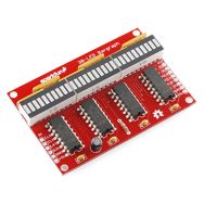
I really like this next kit. I've always wanted to include our 10-segment LED bar graphs into a project, but I'm too lazy to wire up each of the 10 LEDs. And you can't just use one, so then you're wiring up a LOT of LEDs. This kit makes life a lot easier. It combines 3 10-segment LEDs (green, yellow, and red), some shift registers, and a few other components so you can easily control all 30 LEDs with just a few pins on your microcontroller. We've even got an Arduino library and examples to get you started. You can easy daisy-chain multiple displays seamlessly together and make your own custom display.
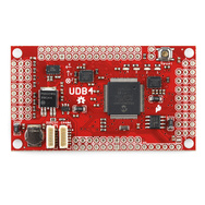
And of course this is the UDB4 that we talked about yesterday. If you didn't get a chance to read the post yesterday, you should check it out. It's taken a lot of work to get to this revision, and the board has come a long way.
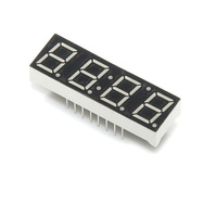
In addition to carrying the 4-digit 7-segment displays in yellow, blue, green and red, we now have them in white. These simple modules work well for timers, clocks, or basic numeric readouts.
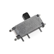
Sometimes it's really hard to find the right part. We've been searching for a good surface-mount right-angle switch and we think we found one. The problem with most right-angle switches is that they tend to lift traces over time because the lateral force of using them weakens their connection. This one has 4 little feet that help to stabilize it. We will start incorporating this into our designs for better reliability.
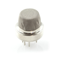
We've added one more gas sensor to our lineup. In addition to our methane, LPG, carbon monoxide, and alcohol sensors, we now carry the hydrogen gas sensor. Use it for detecting hydrogen concentrations in the air. This sensor works with our gas sensor breakout as well.
We've added a new color to our StarBoard lineup. Now we have them in pink. These new versions also have a slick black flexible PCB.
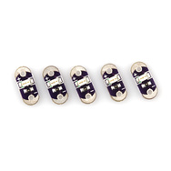
We also have the LilyPad LEDs in pink! So now you have even more colors to light up your next e-textile project.
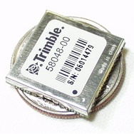
The Copernicus II is the latest iteration of the popular Copernicus GPS receiver from Trimble. It has a fast lock time and performs well in foliage canopy and urban canyon environments.
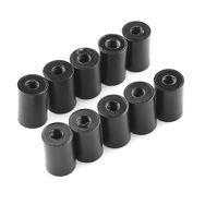
And finally, we have black 3/8" 4-40 nylon standoffs in packs of ten. Now you don't have to think 'should I get 4, or 5 in case I lose one?' Just get a pack of ten and you'll be set.
So there you have it, more products than usual and our longest ever New Product Post Video. Hopefully there's something in here you want/need for your next project. Thanks for reading and we'll see you again next week. Don't forget about Open House!




This is the best Friday new product post video
i have seen since i started visiting sparkfun
I was always confused about what motors to select this helped a lot.
Thanks a lot.
Too many cool toys. Too little money and time. Curse you Red Sparkfun Baron! ;-)
unfortunately, most of the stepper motors are sold out already! don't worry, that was only our partial shipment. we have MANY more coming in November, so feel free to backorder (or notify) and we'll have them in soon.
Great new product post. One little gripe - I think quadrature is not interchangeable with quadratic.
Great video! I always wanted to take apart a stepper but was afraid I'd break it or mess up it's accuracy.
Another thing I've wondered about... Anyone make servos with steppers instead of a DC motor? I'd think they would be slightly more accurate position wise, and then you would have the ability to precisely adjust the speed/direction, plus gain extra torque and holding power.
I'm guessing the added precision wouldn't be worth the extra cost, but I can think of a few applications where it could be beneficial.
I have read that you lose a significant amount of torque capacity by disassembling a stepper. 20%?? Don't take one apart just for fun. Andy
Yeah, I've heard that too, not sure why.
Thankfully, anyone that's REALLY curious can just watch the video now and they don't have to take apart their motor...
Not an expert or anything, but I suppose you loose some of the magnetism of the permanent magnet.
I saw a big magnet used in a gas turbine generator and while they were doing maintenance, they put a chain on sort of a ring around the magnet, I was told that not doing this would cause the magnet to magnetize the surroundings and loose its own.
Not sure if they are related though
actually, i didn't really talk about it TOO specifically, but hobby servos have significantly less accuracy than a stepper. you're basically relying on the linearity of the pot, versus the physical steps in a stepper.
they make dual-shaft steppers that you can attach an encoder on to the other end. that is what you're thinking. these are useful for CNC mills where missed steps might be common and unavoidable.
however, at that point, you might also consider standard dc motors with encoders. there are many choices :-)
Congratulations and thank you for this very interesting video about motors.
I use stepper motors with AMIS30624 I2C controllers.
Nice video!
Protip: The units of "oz-in" is pronounced "ounce-inches", not "ounces per inch". In the case of the largest motor you could energize it, clamp something like a pair of vice grips to the shaft and hang 125 oz (about 7.8lb / 3.4kg) from it at a distance of 1" from the shaft center.
Torque is force multiplied by the moment arm, so it's "force distance", not "force per distance".
Just like on your car - inch-pounds, foot-pounds, Newton-meters, etc.
Sorry, I work in Industrial Automation and for some reason that's always been a pet peeve of mine. :)
I like using "Horsepower-Seconds" instead of boring old "ounce-inches".
By my calculations, 125oz-in = 0.0012 hp-s.
;) My speedometer is marked in furlongs per fortnight too.
I like gigaangstroms (1 GA = 1 m) or attoparsecs.
1 angstrom= 10^-10 meters
Giga= 10^9
so wouldn't a gigaangstrom be .1 meters?
Absolutely, you are correct! My bad.
1 GA = 0.1m = 1 decimeter = 10 cm = 100 mm.
Isn't metric fun! Conversions are so much easier (at least, when I don't screw them up.)
Speaking of misused units... I saw an electronics tutorial on some website... the capacitor and RC circuit sections were talking about 15F and 3F capacitors! God forbid you teach an American SI prefixes.
In many tutorials, resistors are too small and capacitors are too big.
Well, either they are trying to keep the math simple to focus on the concepts, or they are referring to these
They are, of course, trying to keep the math simple. But I just feel bad for the people who build the circuits and get REALLY hot resistors and can't figure out why it's taking 2 days to discharge their RC circuit...
Came here to say this! (Not the working in Industrial Automation part, tho.)
yeah yeah yeah.
if that's the only real gripe people had, then I feel pretty good.
Well there is the "most continuity" line - which should have been "highest resistance less than infinity"...
:)
yes, your explanation is correct.
In the datasheets it's pretty clearly g*cm (or g.cm, g-cm), oz*in, N*cm, etc, not oz/in. Force/distance isn't a unit of torque. I only mention this because the listed incorrect units might trip up people unfamiliar with the subject who are trying to determine their requirements.
On-topic, great detailed teardown! It's always interesting to see the internals of the things one is using.
fixed.
:-)
You kick ass big time, keep up the excellent education!
I got all exited when I saw the UDB40, because I thought they were SATA connectors. Sadly not... Hopefully with the new Arduino Due, somebody will make a SATA shield, so that I don't have to. Arduino + 1TB Hard Drive... :-)
Awesome vid. Basically explains in 1 video that which took me 6 months of forum posts to understand. On the feedback about the stepper: There are drivers that can detect motor stall and report that event as an error (l6470), to the MCU. Also it should be possible to use the Softpot Rotary Potentiometer as a feedback loop on a stepper?
Really great video. Thanks.
Great video, very educational and helpful, got a comment and a 3 questions
Make sure while reading the resistance of stepper coils you do not touch the leads, other wise you'll probably read your body resistance.
1-Whats the use of unipolar vs bipolar?
2-I heared before that you cannot (or its not recommended) to gear a stepper, is this correct?
3-Why steppers need dedicated drivers and a normal H-Bridge won't work (although in the two cases the sequence will be provided by the MCU)?
Lesee...
1) Bipolar provides more torque, but you need 2 full H bridges. With unipolar you can just provide power to the shared line and pull down the coils in sequence via transistors or NPN FETs. You generally need resistors, though, to keep the current levels correct in unipolar drive, so you lose a lot of power if you don't have the voltage matched exactly.
2) I find geared steppers all the time. It's just not as useful as gearing a DC or regular brushless motor because you don't have a nominally constant torque curve, but one that drops off quickly as the speed increases. This limits the power you can generate, but if all you need is low speed torque, this is fine.
3) Dedicated driver chips, as urjaman said, have integrated current control, which is the only way to prevent overcurrent and meltdown of stepper drives if driven from higher than rated voltage power supplies. High V supplies provide current faster, so faster steps.
1- Those 6-wired steppers can be driven in a unipolar configuration, eg. common to ground and power to one or the another coil half (if i understood wikipedia correctly.)
I skip 2nd one, dunno.
3- Again, based on gut feeling and wikipedia, you can drive a bipolar stepper motor with two H-bridges (one for each winding) and if you drive it in the correct sequence it will work, but there are better drivers out there that provide more torque at high speed (constant current), etc.
Loved it. Learned more useful and practical information in 15 minutes about steppers and servos than most hour long tutorials. I'd love to see more of this. It really fits with Sparkfun's overall persona.
Re: demagnetization. I agree the article sounds like an ad but, never the less I have observed several Makers take apart motors and then have problems with them.
Here is a link from Maris at GeckoDrives. He seems to indicate that the problem can sometimes be mechanical due to joint failure or heat. Now we have a mystery. http://cnczone.com/forums/stepper_motors_drives/89992-what_kills_stepper_motors.html
Bill
Without any doubt, tonights show was the best. The tear-downs told me, probably, all I need to know about steppers and servos. More tear-downs, please.
Thanks for the video. The thing I am struggling with is how to attach gears n such to the steppers. I am so interested in these things, but when it comes to linkage, the info becomes scarce and I am somewhat lost. Can you guys perhaps follow this up with some flavor of a making your stuff move stuff video?
check out timing belt pulleys. they attach to the shaft with a set-screw. a good place to look around is mcmaster carr.
so you can do that or do gearing. check out servocity.com.
Here is a link to an article about demagnetization of Stepper motors. http://www.servorepair.com/servo_talk_sample.htm
You mean this link? It reads more like a sales pitch than an objective piece about motor rebuilding.
Saturation is a property of electromagnets, not permanent magnets. Not sure what they're trying to get to there.
As for the disassembly story - permanent magnets don't demagnetize that easily.
I do think however that since tolerances are quite narrow, disassembly can easily lead to misalignment, which in turn will lead to loss of torque.
Overcurrent would be able to demagnetize though: see WikiPedia.
Actually magnetic materials saturate also (steels, etc). Permanent magnets come in a range of coercivities— many can be partially demagnetized pretty easily, using fields no stronger than their own, or even just by removing them from their low-reluctance magnetic circuit (which I guess is what's happening with steppers, but I don't know much about steppers).
You should not take apart a stepper motor. They become demagnetized when you do so. The results will be loss of torque and or failure to work.
The combination of teardown and tutorial for stepper, servo and the full feedback critter was GREAT!
This is the best Friday new product post I've seen yet!
Thanks!
Your best new-product video by far!! Really interesting, I'm definitely adding one of those stepper motors to my next wish list. I actually thought they were smaller :)
About the ROB-10847 and as I said on that product page:
"These are really nice, but what would really put them over the top for me would be steppers with a rear shaft as well- that way we could add encoders, handwheels or similar."
Yeah, I like dual-shaft steppers too, but we couldn't find the right ones. we're still looking.
Thank you Robert and SparkFun. That was very informative. It helped stop me from taking mine apart.
Thanks again.
I may be in the minority here, but for as much as I love a good tutorial/teardown (and this one is really good), I just want to see you discuss the products (and the shenanigans!). Much of this felt like it belongs in the tutorials section.
If I could make a suggestion, if you want to keep the videos as is, a simple bookmark indicating when you are talking about a different product would be nice. Then we can just skip to the next one. 17m49s is too long for me to sift through at work.
Cheers!
Yeah, you are in the minority. In the future, I might split them up. It's been discussed to do the educational one, and then the 'fun' one. It's a lot more work and this is only about 1 hour out of my 40 hour week (believe it or not). It's my smallest job duty actually.
Don't get me wrong, I really enjoy the videos!I am impressed that you get so much done in 1 hour, too! I've done videos in the past and I know how much time it can take. I will just have to live with being yet another type of minority.
Well, thankfully I just do the talking, someone else dose the video portion, so my involvement is minimal.
We're testing the waters here. So far it seems like everyone really liked the new format, so who know what will happen. It just depends on what products we have for the week.
The larger of the two new stepper's is probably about right to drive the azimuth axis of a Dobsonian telescope, the smaller one should be about right for the elevation axis. There are some projects out there using steppers to drive dob's to star track for astro-photography. For long exposures you probably need a third motor to rotate the telescope tube though.
The third motor you mention is to solve the problem called field rotation that occurs when your telescope is not mounted equatorially. However, with Dobsonian telescopes the mechanical and optical axes are typically not in line with one another, so rotating the optical tube assembly will cause issues. Correcting field rotation can be done by rotating the imaging sensor itself, however.
On the dc motor with optical encoder (black and white wheel) why does it need TWO infrared sensors? Seems like it should only need one.
Can anyone explain?
The sensors are arranged so that when one is on the line between black and white, the other is in the middle of either black or white. When one output is transitioning from high to low (or low to high), the other is stable, removing any uncertainty in the direction of movement which would exist with only one sensor.
Given two sensors in what is known as quadrature configuration, one can both detect the speed and direction that something is rotating.
You also can get finer resolution when using two sensors. One sensor would give you one half the resolution that two can give you.
You only need one if all you want to do is to get a report on how far the shaft has turned. You need two if you want to detect change of direction as well.
Thanks for the teardowns, they are great! I hope this becomes a regular feature. Even though it is a long video the fast pace keeps it from becoming boring. For really long videos, you might try having Dia as a co-host to help keep it lively.
And since Robert is in sales, we shouldn't be too picky about the loose use of the terminology.
Oh, I'm not in sales :-)
Yes, I'm not an engineer though, so I am loose with terms, but the general point still gets across (I think/hope).
Is that "think per hope" or "think-hope" hehe ;-)
We need a a sample project for this one
http://www.sparkfun.com/products/10848
I smell a prank...
I always wondered what the servo control board was made of. Is it another micro?