Ultimate IMU
Replacement: None. There's no direct replacement for this board; however, we do have a variety of IMUs in our IMU category. This page is for reference only.
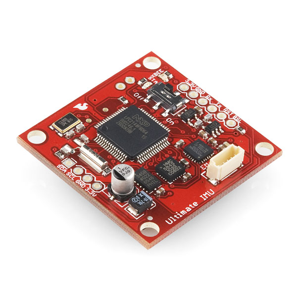
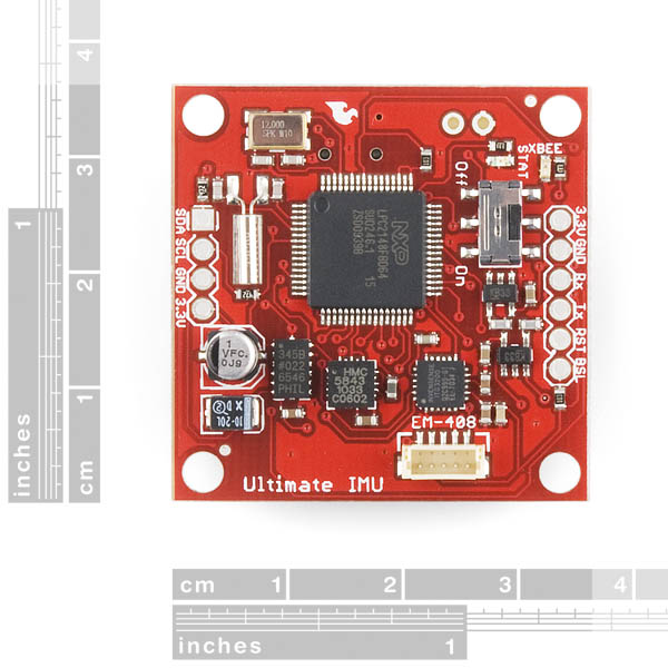
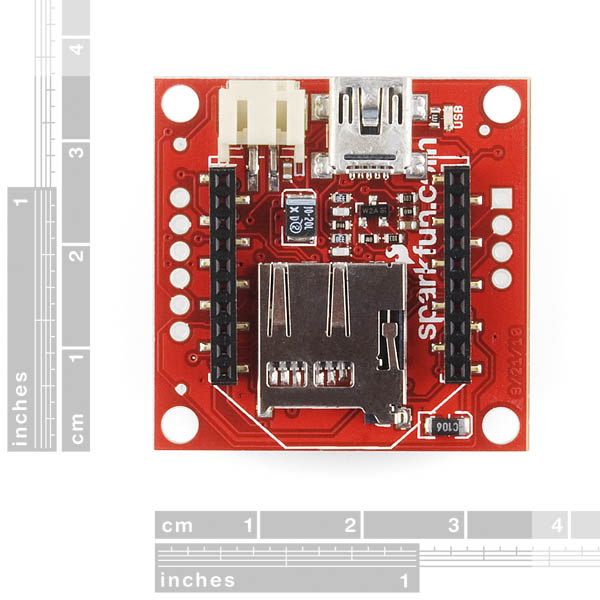
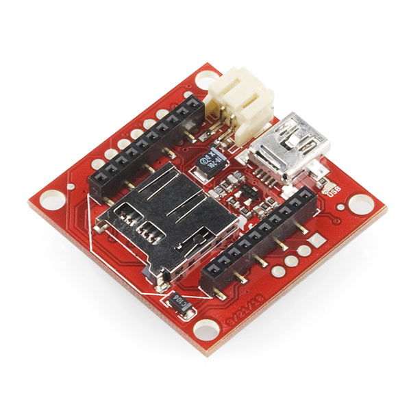
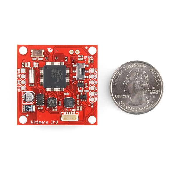
The Ultimate IMU platform combines an ITG-3200 gyro, ADXL345 accelerometer, and an HMC-5843 magnetometer in a single package. In addition, we give you a GPS header, MicroSD socket, and even an XBee header. Control is provided through an LPC2148 processor with plenty of extra memory for custom code development.
Connections for both a battery and XBee module allow you to use the Ultimate IMU in a number of applications.
Note: Check the github page listed below for firmware files and updates.
Note: The battery connector will interfere with XBee pro modules. However, regular XBee modules will work just fine.
- 1.4x1.4"
- Schematic
- [Eagle Files](http://www.sparkfun.com/datasheets/Sensors/IMU/ultimate imu-v12.zip)
- Datasheet (ADXL345)
- Datasheet (HMC5843)
- Datasheet (ITG-3200)
- github page
Ultimate IMU Product Help and Resources
Comments
Looking for answers to technical questions?
We welcome your comments and suggestions below. However, if you are looking for solutions to technical questions please see our Technical Assistance page.
Customer Reviews
No reviews yet.

Hi all, I've been trying to communicate the Ultimate IMU with a Mini Arduino Pro via I2C, but I've failed to do that. The problem seem to be because there is no any ACK response signal from the Arduino at the beginning of the i2c protocol. So, I get the Error 48 and 10 from the Ultimate IMU. I've modified the update function form the source code on this website as below:
char cFLEXIFORCE::update(void){ if(read(values, 4)){ lt_pres = values[0]; lh_pres = values[1]; rh_pres = values[2]; rt_pres = values[3]; return 1; } return 0; }
Can there anyone connect the Arduino with the Ultimate IMU successfully? Please give me some suggestion or the solution. Thank you.
I have bought Ultimate IMU. i was wondering whether we can get the sensor data over I2C???
Very sad that this product has been retired. It's a great all-in-one sensor for those who need a compact IMU capable of wireless comms. I would have loved to see a Version II board with improved firmware. Why was it pulled? Didn't it sell well enough?
Hi , i bought this kit for tracking . But im getting only Euler angles and no accelerometer readings .. Can any one help me out
I'm not sure if you've realised this, but you can configure the device quite nicely. You'll need to download the latest firmware (FW.SFE) file from Ryan Owen's page and copy it to an SD card on the device (you can do this through the mass storage system it offers). When it reboots and starts running it should generate a configuration txt file in the SD card root. Poke around there and you should be able to see several options. You can disable Euler angle output and it will print out the raw sensor data.
I don't think that the standard firmware offers quaternions in lieu of Euler angles. I'm busy working on adapting the chrobotics UM6 code for the Ultimate IMU, but I don't think it's going to be ready any time soon.
Does this offer any GPIO pins?
The board breaks out i2c, as well as the pins required to hard reprogram the device (sort reprogramming is done over mass storage). It's a bit of a hassle, but you could probably add a slave i2c to IO device, or have a second attiny mcu that offers IO and relays it back to the LPC2148 over i2c.
Is there any workaround regarding the interfering with the XBee pro beside using regular modules? I´ve got just some spare pros...
Can't you stick some header pins between the current pins and the xbee pro, which would elevate the radio module off the battery connecter? I guess that you could alternatively desolder the battery connector entirely and run cables to the power source / add a power pigtail connector. That should clear up room for an xbee pro to fit snugly.
I noticed the ITG-3200 clkin (Clock input) is tied to ground, making it use the internal oscillator. Is there a reason this does not use the 32.768khz oscillator already contained on board? This should (in theory) provide more accurate measurements with no extra components.
This could use a windows app to display things graphically. I mean I don't hate terminal programs (personally I use realterm) but its pretty easy to write a VB or C# program to decode this data and display it graphically, have buttons for configuring, etc.
Yes, This costs too much.
http://store.ckdevices.com/products/Mongoose-9DoF-IMU-with-Barometric-Pressure-Sensor-.html?setCurrencyId=1
is essentially the same thing but with the addition of a barometric pressure sensor and an arduino compatible avr for much easier development, all for about $40 less than this board when shipping is considered. When one add's the cost of a bmp-085 to get equivalent features it becomes more like $60 less for the competing board linked to above.
You just don't recognize a great product when you see it. The LPC2148 processor is much better than the Atmega on the mongoose board. Sure, if you wanted to save a couple of bucks, the mongoose board is the better buy. However, if you wanted to implement any kind of control loop or auto-pilot feature the ARM will give you a huge performance advantage.
I agree with SuperFlux on this one. However, it would be even better if this product came with a VFP capable ARM micro, as many filters for localization require large floating point matrix updates.
The Razor IMU (SEN-10125) explicitly states on the product page that it's compatible with (a) the FTDI breakout board, (b) the Sparkfun Bluetooth Mate, and (c) the Sparkfun AHRS firmware. I'm not clear whether the fact that this page (for the Ultimate IMU) doesn't say those things should be taken as a lack of compatibility. Anyone? Is the Ultimate IMU compatible with (a), (b), and (c)?
Thanks!
Yes, they all use the same pin configuration, and the ultiamte IMU has this header on it. You can plug in all three (not at once of course!)
But, the AHRS firmware doesn't work, this uses a completely different IC.
Ok. There really needs to be a link to this page:
LPC2148 USB Bootloader Tutorial
I was completely lost and this page saved me. This board is pre-loaded with the sparkfun bootloader.
After "github" upgrade, the "configuration.txt" was involved, the Ulitimate IMU works fine now. While can't find XBee console for calibration.
Ultimate IMU Configuration
~~~~~~~~~~~~~~~~~~~~~~~~~~
configuration.txt:
log_sensor=1 ( Enabled/Disabled )
log_gps=0 ( Enabled/Disabled )
range_accel=1 (+/- 0:2g 1:4g 2:8g else 16g )
range_compass=1 (+/- 0:0.7 1:1.0 2:1.5 3:2.0 4:3.2 5:3.8 6:4.5 7:6.5 else ? (Ga) ? )
msgs=0,0,0,0,1,0 ( GGA GLL GSA GSV RMC VTG )
euler=1 ( Euler/Raw )
serial=2 ( 0:None 1:Sensor 2:GPS else 3:Sensor and GPS data )
cal_ax=0
cal_ay=0
cal_az=00.00
cal_gx=0
cal_gy=0
cal_gz=0
Hey, guys, I'm trying to contact the tech support or Mr. Owens.
The code downloaded from github doesn't works. There are some files missing (all about uart0). I patched (badly) the code, but I can only read 0xf0 or 0xff at uart0...
Can you please put a link to the original (working) hex file?
For the code, is it made when there is a GPS ???
Hi.
I simply would like to know if the Kalman filter is included in the code.
Thank you
There is a simplified Kalman Filter that can be enabled. The code was based on an example from Starlino, you can read about it here:
http://www.starlino.com/imu_kalman_arduino.html
I would buy this board even if it is very pricy, but not until there will be a manual, a demo with Kalman EKF and/or DCM. What are sampling rates, how readouts of sensors are sychronized? Is there a way that they're able to give measurments taken at the same time, or they are lagging. What are benefits of this board compared to CHR-6DM with same price and programs included?
Is someone using this IMU?
Comes this board with the USB boot loader implemented?
It's funny how just about every part I've looked at Sparkfun recently has comments about the price being too high.
I think this is proportionately way too high - to all the other MEMs devices I've been looking at.
Sad part is, I would buy a lot more parts if they were affordable, unfortunately I'm not going to be able to buy any of these. Honestly, $200!?
Is the LPC Serial Port Boot Loader Interface programmer the best option for programming this board?
Are there any USB based options?
About xbee ability, how can I configure the xbee modules for use with? Examples please!!!
jm
Seriously - vbus doesn't power the unit ? no battery charger and I have to have a better plugged into it in order to power it, even if it's connected to USB ? Seriously ?
How long until Version 2.0 comes out ?
I also have similar questions as above. The price seems really high. This chip has so many unused pins which are not accessible, why is that? What does the firmware do? Is it AHRS? Will you ever release AHRS?
Dear Sparkfun, I love the specs, but how do I get from running an arduino to managing this IMU ? What should I do/read to close the gap ? I don't even understand how this IMU can integrate with a flying machine of any kind. Can it control servos, or does it need to be attached to another unit still ? What's the Xbee for, can it serve as comms platform only or are its digital/analog ports accessible ? What are the configuration options of this unit, and how can it be compared with a setup based on just the 9DoF IMU stick ?
I suppose the way to go from Arduino would be:
-use Ardupilot code
-convert to plain C++ AVR code with Makefiles etc
-generalize a bit the hardware handling code "drivers" for gyro/accel/compass (maybe an intermediate step would be Ardupilot ported to Arduino + 9DOF IMU, I'm in the process of doing this as i've got one but have very few spare time...)
-port the code to LPC2148 MCU
About the servos, either you must use digital servos conneted to I²C but that would mean much wiring in I²C, not toot good for using the bus with fast sensors, an I²C IO expander or soldering wires to GPIO pins and implement PWM.
If one day I manage to have 9DOF IMU + Ardupilot working well I might upgrade to this awesome unit as the HW specs of the ATmega (2k SRAM!!) is the next obvious limiting factor
Perhaps you'll want to add the EM-408 to the list of related products.
I already have a EM-406. Will this connect?
The EM-406 and the EM408 are very similar, but have different power supply requirements, and slightly different connectors.
Check out the data sheets.
em406a user guide
em408 user guide
Logorazorfunnelmatic :-D
It would be great to have access to the JTAG interface for those of us who like to do more than just download code.
Also, it would be kind of handy to have a battery charger.
Lastly, would be nice to have some USB EMI/Static protection included. It's cheap, and easy to include, so why not. It will save the board, especially in dry conditions.
SK
Scott:
Lastly, would be nice to have some USB EMI/Static protection included. It's cheap, and easy to include, so why not. It will save the board, especially in dry conditions.
SK
I agree a USB charger will be nice. You don't really need static protection for most NXP chips, because they have TVS diodes at each pin.
This is really a nice board, but the price is a bit high. In such small package, I don't think it is feasible to fit a 10 pin JTAG connector. But it is possible to break out just SWDIO and SWCLK for debugging.
Size is always an issue when it comes to JTAG connectors.
One thing to consider is maybe two versions of each board. One for development, including the JTAG, more pins brought out, more test points and such - and another - smaller version for actual usage. That way we could do more testing and validation on the larger board, and may even qualify the software for some production uses that would sell a whole lot more than just one or two at a time.
Oh, yea, I told a few guys at Boeing about these last weekend and they were totally depressed. Guess it takes them 24 months to do any kind of IMU. So keep up the good work.
SK
What does the firmware do? There's no clue or documentation on the github page. Is it a full AHRS with a Kalman filter or just sensor reading code?
Wow! That's quite a few sensors. However, the price seems out of line for the components on the board, though not so much for the development costs (I had initially assumed it included a GPS connector)
However, I was disappointed in the number of pins on the microcontroller and sensors that were simply left floating. I'd miss the interrupt pins on the sensors. Also, even a few staggered test pads on the microcontroller would be better than soldering to the device leads.
Still, a pretty awesome board!