×
SparkFun will be closed on Tuesday, December 24th, and Wednesday, December 25th, in observance of the Christmas holiday. Any orders qualifying for same day shipping placed after 2:00 p.m. (MST) on Monday, December 23rd, will be processed on Thursday, December 26th, when we return to regular business hours. Wishing you a safe and happy holiday from all of us at SparkFun!
Please note - we will not be available for Local Pick up orders from December 24th-December 27th. If you place an order for Local Pick-Up we will have those ready on Monday, December 30th.
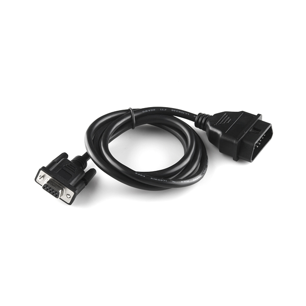
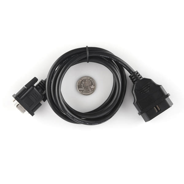
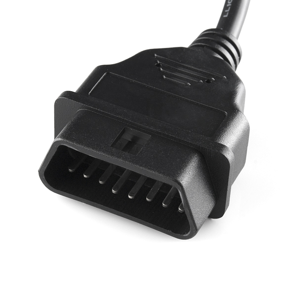
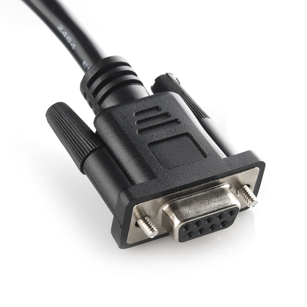
Once you've hacked everything, why not go out in the garage and hack your car? This cable allows you to access the pins on your car's OBD-II connector. It has an OBDII connector on one end and a DB9 female serial connector on the other. The overall length of the cable is 5'.
Note: This cable is not meant to be plugged directly into a computer's serial port. It is meant to plug into some sort of hardware interface.
Here is the basic pinout (OBD-II > DB9 Female)
| Pin Description | OBDII | DB9 |
| J1850 BUS+ | 2 | 7 |
| Chassis Ground | 4 | 2 |
| Signal Ground | 5 | 1 |
| CAN High J-2284 | 6 | 3 |
| ISO 9141-2 K Line | 7 | 4 |
| J1850 BUS- | 10 | 6 |
| CAN Low J-2284 | 14 | 5 |
| ISO 9141-2 L Line | 15 | 8 |
| Battery Power | 16 | 9 |
OBD-II to DB9 Cable Product Help and Resources
Getting Started with OBD-II
October 8, 2015
A general guide to the OBD-II protocols used for communication in automotive and industrial applications.
Comments
Looking for answers to technical questions?
We welcome your comments and suggestions below. However, if you are looking for solutions to technical questions please see our Technical Assistance page.
Customer Reviews
3.7 out of 5
Based on 3 ratings:
OBD2-cable
This cable makes much easier to connect to OBD-connector and gives any hacks professional look. Enough long, in case connector is in some lousy place. Can't really say anything more about it
Works well
The cable transports the power and CAN bus signals without a hitch. I haven't needed the other pins yet. As another reviewer noted, it looks good -- much better than any hand-rolled solution I've seen.
I had some concern when I received this cable due to the OBD-II end being rubbery instead of solid plastic, but that hasn't proven to be a problem with the two vehicles on which I've used it.
I've run the cable under the driver-side floor mat and over to the center console (keeping it out of the way of the driver's feet) and the cable was no worse for wear after a multi-state trip, so it seems to be well made.
The screws on the DB9 end of the cable are occasionally difficult to screw by hand, but I cannot tell if that is due to the cable or the port into which I am screwing it. In either case, using a flat head screw driver to finish the final few revolutions has always worked.
Need full 16 pins so I can get iso, vpw, pwm and can
Need a db25 to carry 16 wires


Does someone noticed that the pin no 4 and 5 of OBD male connector in this wire are short or is it only me?
Digging up an old thread here, but does anyone know whether the cable includes 16 wires pinned out to the obd plug, or only the 9 for the db9?
I am looking for a cable which uses a few more of the obdii pins than are pinned out on this, and was wondering if I could hack off the db9 and pin them all on a db25...
I purchased this cable and I have found a short between OBDII pin 2 and ODBII pins 4,5. Of course I cannot just remove the pin as I need J1850 for my application.
Just heard back from sparkfun and they are shipping a replaced. Very easy and fast service, thanks sparkfun!
I had the same problem with my cable (ordered around 2 years ago) and Sparkfun shipped me a replacement too with no hassle. Great job guys, keep up the great work!
Please consider changing the product name to "OBDII to DB9 Cable". You have an OBDII connector on one end, and a DB9 connector on the other end. There is no such thing as a "serial connector", only serial protocols. While there are serial protocols involved, they are not the RS-232 serial protocols people expect when they see a DB9 connector. Using the term "serial" to describe the product is likely to lead to more confusion.
Seconded. If its got a DB9 and you call it a serial connector, people will naturally be inclined to think its RS-232 serial. Even when you say "its not meant to be plugged into a computer serial port" that almost seems too soft. "It can't be used with a computer serial port" is a bit more to the point, I feel like. Hopefully this doesn't just seem nitpicky, but its important to be clear on this stuff.
-Taylor
Adding yet another nitpick - technically that connector is a DE-9F, not a DB-9. The "B" shell is for the 25-pin-size connectors.
Very true, but no one has a clue what that is. The standard accepted name is DB-9.
The pinout can't be right....Pins 1 and 2 are the J2850 BUS+, and also signal and chassis ground in the current table. The J2850 BUS+ signal should be on pin 7 of the DB9 by process of elimination...I don't have a cable to verify this, though.
I'll double check it, but that's the information we had with the cable.
I want to read my car's speed while in motion. Can I create some type of setup with this cable to send the info to an arduino?
Or do I need extra hardware such as the "Car Diagnostics Kit Retail" sold here on SparkFun?
Thanks in advance!
P.S. Someone please reply lol
The cable simply allows you to interface with a DB9 port on your car. You'd still need either a CAN IC or OBD-II IC to actually communicate with the vehicle. Check the car diagnostics kit to get a bit more info about starting on that.
how much current can be pulled from the 12V?
Charlie
Buyer BEWARE:
My team purchased a set of 10 of these cables to go along with a project we have. We found it extremely difficult to connect to the OBD-II port of some vehicles like the Subaru Impreza or the Honda Pilot, whereas it fits just fine with a Subaru Legacy or possibly other vehicles.
It seems the short side of the trapezoid shape of this OBD-II cable is actually smaller than the actual interface on the vehicles. The pins match up just fine, but it is just too tight.
We have even ended up bending some pins and possibly damaging the OBD-II interface on some vehicles trying to force it on.
We have not found a substitute cable yet, but if you find other options, those might end up being better.
Just tried it with my 2012 Toyota and after dremeling a bevel on the short sides, it went on and off ok. Without the bevel it wouldn't go on.
Thanks for the information and sorry for the problems.
If anyone finds that these don't fit well, please don't force them, and contact our Customer Service department; we'll be happy to arrange a return if they don't work for your application.
Neat! I highly recommend buying an STN1110 for ~$10 for anyone wanting to dive into your cars OBD system - otherwise, you would have to buy the standards for a lot of these bus protocols which can get pretty expensive and tedious (unless you really love reading about low level bus protocols).
Any chance Sparkfun might carry them (STN1110) in the future?
Sparkfun OBDii to UART: WIG-09555 OBD-II UART
Is this the correct cable to connect an OBD II port to a DEV-10039? (Arduino CAN shield). It looks like it has the same pinout as the cable that skpang sells on their site.
Yes, they go together.
Why is there a signal ground? It looks like all those signals are differential...
This is sadly not a "standard" ODB-II to CAN DB9 cable. For example, it WILL NOT WORK with the AVR-CAN Sparkfun also sells. (Although I have not tried it, it's obvious based on the pinout here and the AVR-CAN schematic.)
If you search Google and Google Images for "CAN DB9", it's pretty obvious that lots of things use the AVR-CAN-style pinout, and not the one used by this cable. I'm not sure if there's an actual standard for this, though.
At any rate, a note that this won't work with the AVR-CAN should be added.
It's not a CAN cable, it's an OBD-II cable. OBD-II contains CAN but it also contains several other protocols. The pinout of this cable matches all the other OBD-II to DB-9 cables I have seen online.
http://www.gridconnect.com/canusblight.html
I recommend gridconnect.com for any CAN to USB or serial port needs. I've worked with their USB-CAN adapters and software and it is the best-performing for the price. The API is relatively simple and for $259 you can get drivers and source code (in C) for windows. The link listed above is a simple serial-can bridge to work with teraterm or hyperterminal
This area interests me greatly, but I have yet to find a good source for information on the different signal protocols. Does anyone have information on converting the various protocols to TTL or RS232? Preferably ISO 9142-2. I can also not find any good information on the packet formats for each protocol.
The easiest way is to use the ELM327 chip. It handles low level protocols automatically, and converts the vehicle bus to a standard RS-232 format. Otherwise you need to obtain the standards document for the bus topology you want to access (SAE, CAN, ISO) and read out the timing diagrams.
Each bus (SAE J1850 PWM/VPW, ISO 15765-4, SAE J2284, ISO 9141-2, ISO 14230-4) has a hardware layer header for messaging, and SAE J1979 also has additional packet framing data.
I paid for the SAE's OBD-II (J1979) standards document, but for most of the more common PIDs you can find the information you want online. If you want manufacturer specific PIDs (like Ford's internal codes for the RAP module, etc.) be prepared to have some difficulties. The individual extentions to the standards are extremely proprietary and licensing them for use can cost as much as $10k-20k.
Everyone's points are noted.
I fixed the pinout, it was incorrect.
Yay! Thanks for dealing with our nitpicky-ness! :)
Don't you mean J1850, instead of J2850? Is this for connecting to the Chinese ELM327 clone boxen?
my guess; we can't connect this cable to computers serial port, is it true?
I'll add a note, but no. Battery power (12v) runs on this cable and won't play nice :-)
It's more designed for hooking up to some sort of hardware interface.
thanks for information.