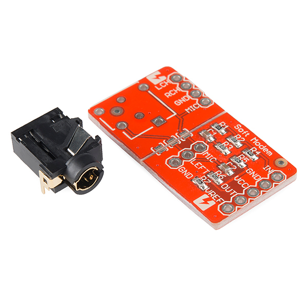
Audio Jack Modem for iPhone and Android
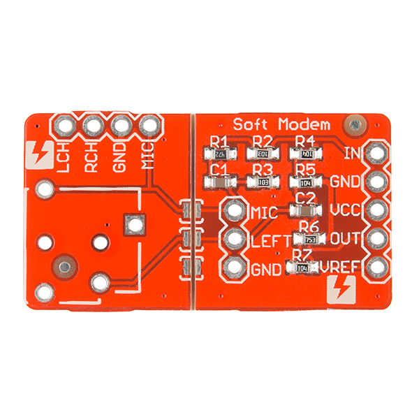
This serial modem brought to you by Switch Science allows you to interface an Arduino board with your iPhone or Android smartphone through the audio jack. Now you can integrate your smartphone into your next embedded project. Some software is required on the phone side, and of course there is an Arduino library.
Because the modem and supporting software exploits a connection originally intended for audio, some corruption of the serial data is to be expected from time to time. It's recommended that you keep this in mind when writing your code. See the links below for more information on the board, the Arduino library, and how to implement it.
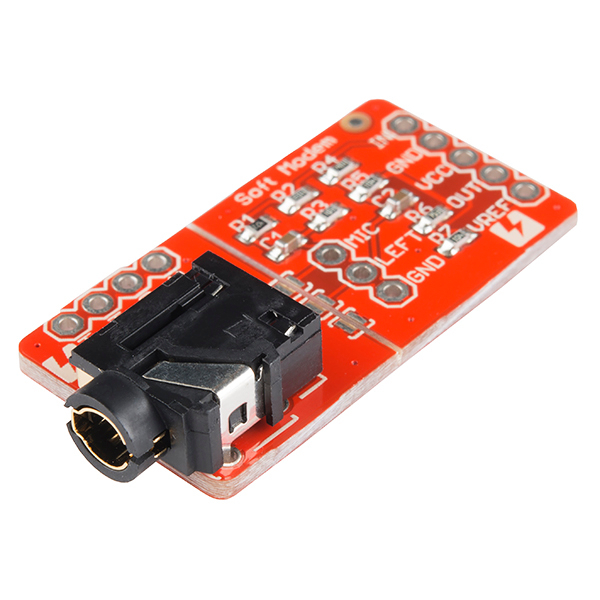
Note: A standard 3.5mm stereo headphone cable will not work correctly with this board. You must use the special 4-pole cable such as you would find on a wired headset. The audio jack shown does come with the board, but is not soldered to the board.
Audio Jack Modem for iPhone and Android Product Help and Resources
Core Skill: Soldering
This skill defines how difficult the soldering is on a particular product. It might be a couple simple solder joints, or require special reflow tools.
Skill Level: Competent - You will encounter surface mount components and basic SMD soldering techniques are required.
See all skill levels
Comments
Looking for answers to technical questions?
We welcome your comments and suggestions below. However, if you are looking for solutions to technical questions please see our Technical Assistance page.
Customer Reviews
No reviews yet.


Any possibility of selling the TRRS jumper cable or jack to go along with this product?
Like this:
http://www.amazon.com/Stereo-Circuit-ThinLine-Audio-Cable/dp/B004QP0D5M
and then the jack from this kit sold separately.
Thanks!
If and when the phone that this is communicating with rings, does it become an issue? Would you get garbage data from it, or is there a simple way to handle it?
Not all modems are telephone modems. This one isn't. See http://en.wikipedia.org/wiki/Modem.
I think Member 264666 was concerned about the ringtone sound playing over the "headset" (modem), and not any sort of telephony-specific interference.
Basically, this connection is repurposing the audio connection from the phone. What happens when some regular audio plays suddenly? This could happen when you receive a call, a text, or a notification from one of your apps or the system (e.g. low battery).
I would imagine that there is the potential for garbage data to be generated in such a case, but I suspect that slight corruption of the intended data is more likely. If possible, it might be best to mute everything else before using this.
Old thread, but chiming in incase someone else has this issue. The app running on the phone is suspended and receives a notification of the incoming call. It easy to stop I/O and perform a check at that point.
Thanks, I was asking about incoming calls and such. I ended up working with wifi instead of this :D
Hi, all !!!!!
Could you indicate the true functional Android source code for current android version ?
That´s all folks !!!! Sincerely...
I am developing a tv remote for Seniors Originally I wanted a wireless way to transfer tv code algorithms from smart device linked to a web database to ultimately transfer <4k from smart device to my remote. Is this possible/advisable/accurate? Can this be done on iOS and android smart phones and tablets and pcs? If so my cost other than Jack+cable is all there is? Thanks
Hi, Has anyone successfully used this board on a project. I can't seem to find a clear or good example on code to interface with iOS or arduino. Any help is appreciated.
Hi. Is there enough power available to support a 3V sensor? Or are batteries required? Thanks
hello, i trying to send digital data fro arduino to android phone, i got this error chk error skipped -1000 in android terminal app r119 can anyone suggest me, how i can solve this error?
so i just received one of these, and i can't get it to work. i'm using the android androino program linked above, and the correct sketch with softterm-005 and i keep getting a "Msg Received msg=-1000" in the "Received:" portion of the android program.
In my logcat for android i'm seeing this "decodeFSK():message=-1:111111111111111111111" followed by this "decodeFSK():message number=-1000:11111111111111111111110000011000"
this leads me to believe that the arduino portion of this is somehow messed up. i hope my board isn't bad. anyone have any ideas?
Hi,
Anybody has tried connecting multiple modems to Arduino? At first I thought it would just be the changing the code to work on different TX,RX ports, however that was not right as Softmodem lib depends on timer2. I need to have two modems in my project. Please let me know if you have a library that supports it. TIA
How to transfer stuff from iPhone to Android? http://www.leawo.org/tutorial/how-to-transfer-files-from-ios-to-android.html
Any chance for an Eagle CAD file?
As this isn't a SparkFun design, you could try tweeting @arms22 , see if he's willing to share the files, or see if member ssci can make them available.
If it's of any use, there have been at least 4 revisions of this. The v1, a prototype v2, the v2 ( which may or may not be what this product is :) ) image of all 3, top to bottom and the v3 ( fixed silkscreen? see other comments in this product page. )
A schematic for v1 and eagle files for v1.
A schematic for v2 prototype and board image for v2 prototype
I think the v2 prototype and this product (be it v2 or v3) are pretty similar other than breaking out the remainder of the audio plug pins on the smaller board section. There's really not much going on with this board - all the magic is really on the software side on both the Arduino and the smartphone OS of choice.
This product could really use some documentation luvin' - just got one to help me debug a problem I'm having in a device, and I am pretty lost getting it setup I must confess.
Not that I have even gotten to the code part, but for starters, it looks like there is a new version of the library available (005) at https://code.google.com/p/arms22/downloads/detail?name=SoftModem-005.zip
So far, this page is the best documentation I've found -> http://arms22.blog91.fc2.com/?tag=SoftModem. It references the new library, shows a nice picture of the board wired up without any complicated transistors, resistors, etc. that I've seen in other examples.
I've
Hello, as already posted before, I have 2 different version of this eval board. Is it possible to get the scheme of this board?
Where can I find android terminal program to communicate with this HW? (all stuff is removed)
can i check whether this DEV10331 is come with all the components as shown in schematic or only the blank PCB?
Hello, I ordered 2 of those from a reseller. They are more or less the same, except the pcb of the first board I ordered is rounded and the FSKIN and FSKOUT pins are inverted.
I have an Arduino Nano and I connect them using the following instructions: FSKOUT → D3 GND → GND VCC → VCC FSKIN → D6 AREF → D7
First of all, they are all correct?
Then... I tried the androino application from website http://androino.blogspot.com/ And it is not working.
I am using this cable http://www.cdiscount.com/high-tech/accessoires/cable-audio-video-cd23384/f-1062802-auc5412810123384.html It provides 4 rings.
So I tried to perform some hardware check. I tested the reception of data incoming from my pc to Arduino using this simple tool: https://github.com/NeoCat/FSK-Serial-Generator-in-JavaScript That allows to modulate bytes in FSK. I am able to receive data correctly. Only the first card can correctly receive data.
Then I wanted to try to send data to my PC from Arduino. I just connect my speakers or a tweeter to see if something is received... Only the second one is able to do it...
Is it necessary to build a custom cable to cross microphone and speaker lines?
Unfortunately everything I've been able to find for a cable are both too long and too expensive. My solution was free for me, but if you actually use your iPhone earbuds, then this is a $30 solution.
Handy info from this page: http://www.zerologic.com/blog/iPhone-Headphone-plug-pinouts.html
And my finished product: pic.twitter.com/OPBHGgGb
Do you sell just the 4 pole jack without the board? thanks
I finally found where you can get only the 4 pole jack:
http://parts.digikey.com/1/parts/103604-conn-3-5mm-audio-jack-4-cond-pcb-sj-43514.html
Do you sell just the 4 pole jack without the board? thanks
Does somebody know if this is possible using the board: Not connecting the iPhone directly via the audio jack but connect a microphone to the breakout board and play the modulated sound on the iPhone speaker.
It should work !!! We have done test using direct "sound coupling" (I mean speaker-microphone) and the encoding/decoding algorithms work pretty well. More information at our project website http://androino.blogspot.com/
The image shows 4 connections to this board: FSK IN GND VCC FSK OUT
I understand GND and VCC, but can someone explain to me what exactly is on FSK IN and FSK OUT? Will these be analog signals? What are the specs of the Frequencies used in FSK here? Any chance these are one of the Bell standards? Any chance the voltage and FSK in/out are RS-232 standard?
Check the source code for the library for a lot of your questions. It has the frequencies for the high and low signals used in binary frequency shift keying (FSK), which is whats going on with the modem here. As for the signals they should be digital according to the notes on arms22 blog and the board manufacture website. Also, I would advise googling frequency shift keying on google, pretty sure that would give you a better grasp of whats going on here, and that seems to cover your last two questions. A wikipedia article would probably cover your curiosities regarding your last two questions there. Hope that helps!
Related project: TribeDuino. Decodes a Korg Monotribe firmware update that's encoded as an audio file, in real time, using frequency-shift keying.
There should be an IOIO for Ipod touch like there is for Android...
Too bad Apple is proprietary crap, eh?
Is this RX and TX or only one way?
Is there any sample code for android using the modem?
Will this work with a first-generation iPod Touch?
I have a n00bie question here:
I'm assuming the Mic, Left and Gnd hookups are optional to solder up since they are provided by the audio jack. Is that a correct assumption?
I gave my board a try last night and cannot receive from / transmit to my Android SoftTerminal application. Not sure where I've gone wrong. I simply soldered on the audio jack and some headers for the FSKOUt, GND, VCC, FSKIN, VREF.
I appreciate any help.
Hi! I just started using this Audio Jack modem and I can definitely receive and send information (seen through SoftTerminal) but I'm trying to write a simple Android app controlled by what's being sent through the jack and am having trouble accessing the information. Does anyone know what Java classes or libraries I should be using to access the information? Any help would be appreciated!!
You might reuse some code from http://code.google.com/p/androino/ and find more info at http://androino.blogspot.com/
Total n00b question: I'm having problems getting this board to work at all. The URL that came with the kit is http://www.switch-science.com/trac/wiki/ARMS22-SOFTMODEM-HOWTO but the wiring instructions seem a little out - it references connecting "AIN1" to pin D7 on Arduino but there is no AIN1 out on the board - does it mean the VREF pin on the board? Is AIN1 a reference to the pot that was ARMS22's original schematic?
Thanks for any insight!
So it looks like I had a cold solder joint on the pin header for FSKIN. Fixed that and can now receive data from the iPhone no problem. Works great!
However, I can't send data from the Arduino to the iPhone. I checked my pins with a meter and have a good connection from the FSKOUT pin on the board, to the MIC pin on the board and also from FSKOUT on the board all the way thru to the 4th, top ring of the iPhone cable.
If i connect a piezo speaker to the FSKOUT and GND pins on the Arduino side of the modem board, I can "hear" the data transmit from the Arduino to the board. If I connect the piezo to the GND and MIC pins on the iPhone end of the modem board, I don't hear anything when I send from the Serial monito - so it looks like the board itself isn't transmitting to the iPhone. Is there anything I can do to test further? Am I missing something obvious?
Thanks for any assistance!
Pacino, any luck getting this working? I ordered some of ARMS22 boards via batchPCB but my thru hole components I had on hand are to big (waiting on next order) and I have a short or some problem on the first one I soldered up. I ordered one of these as well and should receive it tomorrow so I will test it asap and post back here. If you want to reply with your email I'd be happy to send you one of the boards I got from batchpcb (has a place for the pot and ain1 on the arduino side header).
anyone got this specific board working bi directional with the provided library?
Charlie
Thanks for the kind offer Charlie! I still haven't managed to get Arduino to iPhone transmission working with this board. I'm thinking there's either something missing in the instructions (they look like they were written for the original board that had a pot) or there's something wrong with my board itself. Unfortunately I don't have the right tools to really test further (outside of a multimeter).
Let me know how you get on with yours!
cheers,
P.
Pacino, I got the board today and gave it a test. It works great! I have communications both ways! I'm ordering a few more :) I hooked D7 up to the aref line and it seems to be happy. Next step for me is to send this noise over a radio :)
Charlie
Sorry to add this months after your message, but can you elaborate on how you are using this? Are you just using the Arduino C++ code with the iPhone code or something else?
If I connect this to Arduino, the VCC goes to 5V?
Have any of you seen http://www.squareup.com? In short it is a credit card reader that uses the audio port to process credit card payments.
This appears to be this project in production to some degree. My guess is the original idea probably came from this. Either that or they owe someone some serious cheddar as well!
if you open up a square card reader, you'll see that its much more inspired by 80's hacker tech. you could probably open up sound recorder and if you spooled a cassette tape through it, listen to it as well. its seriously a mono tape deck head and a resistor.
I'll have to try this and see if it works!
Oh. I thought this was one of the April fools day jokes.
So I dug around a bit and it seems that the first person to do it is actually this guy here http://hackaday.com/2010/02/01/android-audio-serial-connection/
I did something similar, but which requires a lot less hardware and looks a lot like this product at http://hackaday.com/2010/11/10/android-talks-pulsewave/
Here's a picture of the unit I sent to Sparkfun for evaluation. http://spirit-plumber.com/minimodem.jpg
I understand sparkfun has a lot of products and stuff can get lost in the pipeline, but i ask that they start a conversation with me re: attribution for this.
This is based off a design from a blog called arms22, but he based his basic design off a book "iPhone Hacks" http://oreilly.com/catalog/9780596516642 Chapter 12 Hardware Hacks section titled "Connect a Serial Device to Your iPhone—Without Jailbreaking!" Although they based theirs was targeting a different microcontroller, arms22 made a library for the arduino called SoftModem that lets you interface from the arduino instead of the microcontroller the book used.
Thanks for using my design! You can find the original schematic at http://www.robots-everywhere.com/re_wiki/index.php?title=Serial_on_Android_using_the_audio_port as was featured on hackaday a while ago, circa november 2010. This is a picture of the prototype ( http://www.robots-everywhere.com/minimodem.jpg ) and you can download the software from the Android Market by looking for re.serialout and emailing me for how to integrate it into your apps.
I however note that this page isn't crediting me anywhere, please correct this.
Thank you in advance!
That anyone is squabbling on here about who invented this thing is really amusing, since nearly identical designs pre-date the iPhone, and even the birth of some of you. Ever hear the term "prior art" ?
It is bad idea for you to state that the design was stolen from you. Our company is the manufacturer of this module, and we manufacture the module under a license from arms22.
He first published his idea and experiment on a blog page on June 19th 2010. You may not able to read the page because the page in Japanese text. You can also confirm the supporting iPhone app source was uploaded on his google code page on Jul 2010.
I noticed and put up a comment with my findings that someone did it first in Jan 2010 :)
As an aside, I have a simple solution for your low baud rate and occasional desync, that I use in my module. Perhaps you would like to compare note.
redacted
Right. When you do not understand the purpose of a device, try asking a question instead of rushing to reveal your ignorance.
And yet ozmo, instead of shedding some light on things yourself, you chose to belch forth smoke and noise.
As for myself, this device looks very reminiscent of the microcomputer to FSK cassette tape interfaces of the mid-1970's. I'm not knocking it, although why one would want such an interface to an iPhone escapes me. The iPhone seems like a poor choice given all the less expensive and more open platform alternatives in the world. I suppose it is ubiquitous. If I wanted a quick and dirty interface to an iPhone, maybe to a handy-talkie or something, I suppose I might cobble up something like this, I just don't see myself wanting to. To each his own.
I think the interface is aimed at someone who wants to prototype something that needs a connection from an iPhone to an Arduino without the fear of burning out an expensive port on the iPhone. At least that is why I got an IOIO for Android, so this device seems like a good idea to me. And yep, a $150-200 Android phone gives you GPS, Wifi, Bluetooth, even GSM/3G if you want, but maybe you just want to send periodic short messages with an xbee instead of burning battery time with overkill radios. For which this is a cool cheap little device...
I built one of these in January based off the schematics I found on the arms22 blog http://arms22.blog91.fc2.com/blog-entry-350.html and it works fine. One thing to note though, the version of the library I found in his google code repository http://code.google.com/p/arms22/ only works with the Arduino's that have an ATmega328. I could not get the library to function properly with my Arduino Mega, but I did get it to function properly with an Arduino Fio. It has to do with the specific interrupts the library uses. I see no reason it couldn't be made to work with the Mega, but at this point, it only works out of the box with the arduino's using an ATmega328. If anyone has any updates to this let me know, it would be nice to use this with a Mega as well.
I am also working on an iPhone app for a school project that uses a XBee network for communication. Hence why I am using a Fio. https://github.com/ashgti/Sys-Engineering is where I am keeping my code.
I am after this concept since some weeks now.
There is a few projects that I know to exploit the audio jack for communication:
- Hijack
- Tin-Can
- HMB-TEC
Hijack project is a university development which have not released any app on the Apple Store. But look promising.
Tin-Can does have an application, but honestly, is not rich featured, it is more like a concept proof.
HMB-TEC has beatiful and amazing apps like iMultimeter for iPhone, but they doesn't reveal the insides of their custom communication.
So, I am looking for some app which is open and more universal, and with the first purpose to be a platform for tinkers and makers.
Does anyone knows about such app for iOS?
For description, see http://www.switch-science.com/trac/wiki/ARMS22-SOFTMODEM-HOWTO
To see the schematic, use this link:
http://www.flickr.com/photos/arms22/4821347734
Wayne