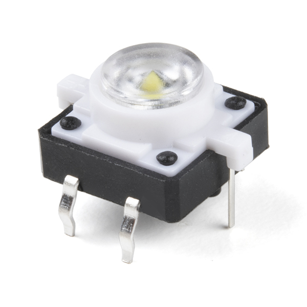
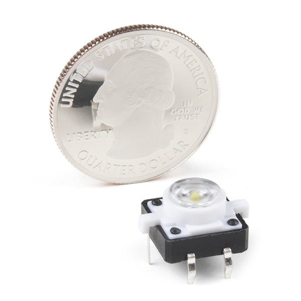
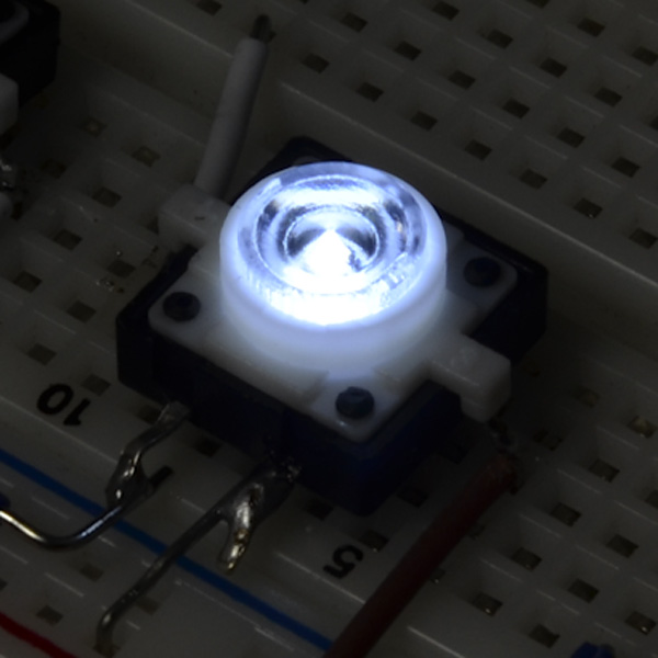
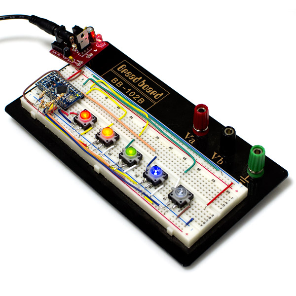
This is a simple LED-illuminated tactile button with a clear cap. It's just like a basic tactile button, but it lights up white! So now you can get visual feedback, or light up your project. These have a 12mm body and are rated for 50mA. They don't easily fit into a breadboard, but check below for a breakout board. We also have these in a a variety of colors, check below to see the others.
LED Tactile Button- White Product Help and Resources
Button and Switch Basics
May 7, 2013
A tutorial on electronics' most overlooked and underappreciated component: the switch! Here we explain the difference between momentary and maintained switches and what all those acronyms (NO, NC, SPDT, SPST, ...) stand for.
Core Skill: Soldering
This skill defines how difficult the soldering is on a particular product. It might be a couple simple solder joints, or require special reflow tools.
Skill Level: Rookie - The number of pins increases, and you will have to determine polarity of components and some of the components might be a bit trickier or close together. You might need solder wick or flux.
See all skill levels
Core Skill: Electrical Prototyping
If it requires power, you need to know how much, what all the pins do, and how to hook it up. You may need to reference datasheets, schematics, and know the ins and outs of electronics.
Skill Level: Noob - You don't need to reference a datasheet, but you will need to know basic power requirements.
See all skill levels
Comments
Looking for answers to technical questions?
We welcome your comments and suggestions below. However, if you are looking for solutions to technical questions please see our Technical Assistance page.
Customer Reviews
4 out of 5
Based on 1 ratings:
It's Pretty Good
The Button and LED work just fine, but if you are going to use on a breadboard the LED's power prongs are VERY inconvenient because they go into the DIP and the power prongs don't fit well into any breadboard slot. I am going to buy the breakout board for it and I recommend that others do too in order to make it more "breadboard friendly" and add male headers to it.
https://www.sparkfun.com/products/10467 breakout board
https://www.sparkfun.com/products/116 headers


Can you make/get a LED Tactile Button with an RGB LED? Imagine the possibilities!
12vdc?
has anyone found a good pin diagram for this button?
Are these double pole, or single pole?
the manufacturer you will find, try to google "khan.cn"
since sparkfun isn't doing a good job of providing data for these buttons... this seems to work best for me:
white led juice = 3vdc 15mA
button = 12v
button current max = ???
What about fitting into a protoboard? Fingers crossed. We shouldn't need a breakout board for something this simple.
On the contrary. After receiving mine, it is obvious that these do actually need a breakout board to work with a breadboard. The pins line up in a way that makes it pretty much impossible to stretch across enough rows to separate them, and they don't properly span the open row in the center. The breakout board is a dream, though. Highly recommended.
Also, I am powering these from the Arduino off of a PWM pin. I've written a very small sketch that turns the LED on when you press the button, then starts to fade it out after about 20ms. I haven't figured out yet how to interrupt the fade-out process to light it back up if you press it again, but I'm working on it (software interrupt?). If you want a copy of the sketch, let me know.
I would love these in an opaque lens like the red, green, and orange lights. The clear lens makes this one pretty harsh.
Has anyone actually tested the voltage these can run with? I can guarantee a quick flashing of colors and then smoke a nice smell to go with it at 9v.
I just want to make sure I've read that datasheet right, they are saying the LED's V-fwd is 12V right?
Nope, I believe that's the switch rating. The LED lights at around 3V.
For those making a footprint I found a full set of measurements (though no more data) on the manufacturer's site: http://www.omten.com/eng/showpro.asp?id=504
Do you have the Eagle footprint for this?