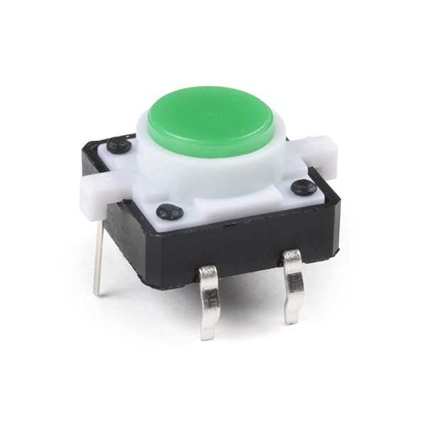
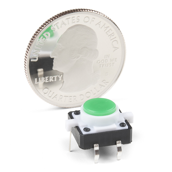
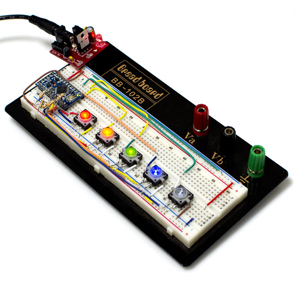
This is a simple LED-illuminated tactile button with a green cap. It's just like a basic tactile button, but it lights up green! So now you can get visual feedback, or light up your project. These have a 12mm body and are rated for 50mA. They don't easily fit into a breadboard, but check below for a breakout board. We also have these in a a variety of colors, check below to see the others.
LED Tactile Button - Green Product Help and Resources
Button and Switch Basics
May 7, 2013
A tutorial on electronics' most overlooked and underappreciated component: the switch! Here we explain the difference between momentary and maintained switches and what all those acronyms (NO, NC, SPDT, SPST, ...) stand for.
Core Skill: Soldering
This skill defines how difficult the soldering is on a particular product. It might be a couple simple solder joints, or require special reflow tools.
Skill Level: Rookie - The number of pins increases, and you will have to determine polarity of components and some of the components might be a bit trickier or close together. You might need solder wick or flux.
See all skill levels
Core Skill: Electrical Prototyping
If it requires power, you need to know how much, what all the pins do, and how to hook it up. You may need to reference datasheets, schematics, and know the ins and outs of electronics.
Skill Level: Noob - You don't need to reference a datasheet, but you will need to know basic power requirements.
See all skill levels
Comments
Looking for answers to technical questions?
We welcome your comments and suggestions below. However, if you are looking for solutions to technical questions please see our Technical Assistance page.
Customer Reviews
No reviews yet.


The drawing in the datasheet for this part contradicts itself. In one angle it, it reports that the distance between the clip pins is 4mm. From another angle, it indicates that the distance is 5mm. To further confuse things, the Sparkfun-supplied 3D model has the pins 4mm apart, but your Eagle footprint has the pins 5mm apart. Is your eagle footprint wrong, or is your 3D model wrong?
If the 3D model uses 4mm, it is wrong. I made a package based on the switch before SFE included theirs in their library, and the pin distance is 5mm. Their breakout board also uses a 5mm distance, by the way. Good example of when not to trust datasheets blindly :)
Cool- thanks for confirming! @Sparkfun, I'll update a fixed 3D model to your github repo ;) I'm fixing it anyways.
since sparkfun isn't doing a good job of providing data for these buttons... this seems to work best for me:
green led juice = 2vdc 50mA
button = 12v
button current max = ???
I'm trying to make an Eagle library part for this switch, but the manufacturer mechanical doc does not describe the pinout. Can someone out there tell me which pins connect when the button is pushed, which pins are anode/cathode for the LED, and what is the relationship between the switch pins and the LED connections? Is there any marking on the switch? I think I can see a faint + sign on the white plastic of one of the LED pins. Is that true?
Did you find/make your Eagle library part? I am looking for one too.
Thanks.
According to the datasheet, "Operating switch is unhindered, rhythmed, and there is not palpable clag." This really sets this thing apart from the tactile buttons I have had to use in the past. Or maybe that is common on newer parts and I had just not seen it before.
yes ok
Whos is the manuf ?
the data sheets says it only works down to -10C.
I would like to contact them and see what is the reason for -10 and not lower. If its just a matter that the led may not sustain its current brightness i can live with that.
But if its a matter that it gets to brittle then that is a whole other story.