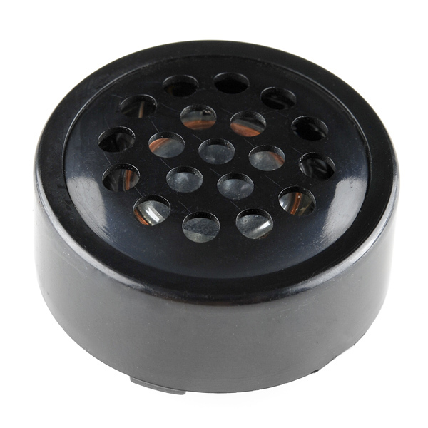
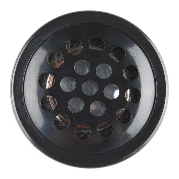
This through-hole speaker is great for projects where you need something that sounds better than a piezo buzzer but don't have room for a full-blown speaker. This 30mm diameter speaker is encased in plastic and will handle about 100mW of power.
- 8 ohm
- 0.1W (0.2W max)
- 30mm diameter
Speaker - PCB Mount Product Help and Resources
Core Skill: Electrical Prototyping
If it requires power, you need to know how much, what all the pins do, and how to hook it up. You may need to reference datasheets, schematics, and know the ins and outs of electronics.
Skill Level: Noob - You don't need to reference a datasheet, but you will need to know basic power requirements.
See all skill levels
Comments
Looking for answers to technical questions?
We welcome your comments and suggestions below. However, if you are looking for solutions to technical questions please see our Technical Assistance page.
Customer Reviews
3.7 out of 5
Based on 3 ratings:
Very quite
5v won't get you anywhere with this. ONLY for PCB mount, too big for a breadboard. Don't buy with SMD boards.
Decent small speaker
Decent sound quality for the price / size. Fits in a breadboard (you gotta angle it, or stick one of the leads into the rails.) Won't be the loudest thing in the world if you just hook it up directly to an arduino. I haven't messed too much with amplification. Getting a few more just to have around.


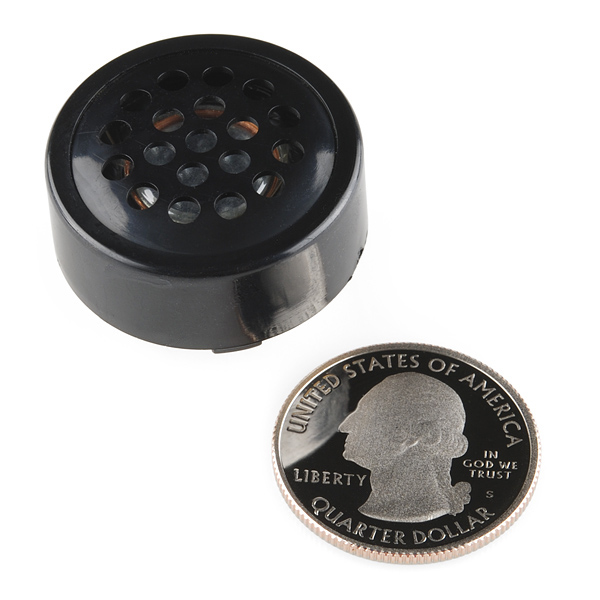
Whoa. That is one shiny new quarter!
( Also, nice speaker. )
Looks to me like he's blowin smoke !!
our photographer bought some uncirculated quarters just for you guys...
Any marketer worth his salt knows not to outshine the central product with side accessories!
Actually, the complete opposite. This is the reason you see so many attractive females selling products.
Reminds me of the ones you used to see on modems.
I'm in the middle of a project where I'm putting an Arduino-compatible in an old external 28.8kbps dialup modem enclosure (U.S. Robotics) to have it playback a pre-recorded 'dialup sound' .wav on demand. I tested many speakers that I had in my parts bins, but was unable to find any that replicated what I remembered the authentic sound to be. Finally, when I sucked the original speaker from the scrap board, I was instantly gratified by it's comforting and nostalgic acoustic properties.
I wish I had known SFE carried these, as I could have spared the original board. I'd better order a couple now, just in case!
I know very little (so far) about crafting electronics. Is there a simple tutorial for connecting this speaker to a 3.5mm headphone jack for use with an MP3 Player? I'm working on a PIPBOY 3000 and this would be perfect for that.
There's very little to it - though keep in mind that if you hook it up directly, it's probably going to be more quiet than if you added an amplifier.
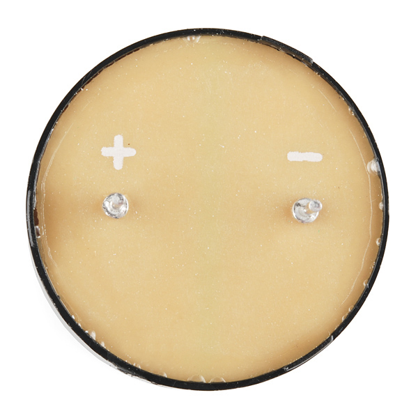
The speaker only has two pins, one is labeled - (minus/negative), the other + (plus/positive). There's some intricacies there, but suffice it to say that you should connect the minus to the sleeve, and the positive to either the tip, or the ring. If you reference the image in Audio Plug - 3.5mm, the sleeve is the really big pin with the little bits sticking out (used to clamp down onto the wires, while the tip and ring are the other two pins.
Note that this is for a single speaker, and you would only get sound from one channel; left or right. If you're using two speakers, you can simply connect both - pins on the speakers to the sleeve, and the + of the left speaker to the tip (pin coming out of the 'middle'), and the + of the right speaker to the ring.
If you wanted to use a single speaker, but get sound from both channels, i.e. stereo mixed down to mono, you would need a more complex circuit; while you can connect the + to both the tip and the ring, phase differences between the two can cause sound to get canceled out strangely - YMMV based on what's being played back :)
Good luck with your project!
Ha, I just pulled this exact speaker out of an old desktop computer.
Can this be driven by an Arduino and can I use your Mono Audio Amp Breakout - TPA2005D1 with it?
Can this be driven with an Arduino?
Yep. Just hooked one up to test it out. Less loud but also much less tinny than a buzzer.
This looks like the same speaker on the ThinkGeek evilTrons, ya?
The video says 0.1 inch spacing on the pins, but it sure looks like it's a multiple of that, maybe 0.6 inch. Those leads look a little thick to be putting in a breadboard too - seems like it would take some of the grip out of any holes it was in.
'0.1" spaced' is a very common phrase to denote exactly that, a multiple of 0.1".
Read the datasheet! Yeesh.
They're 1mm pins, normal 22ga breadboard wire is 0.64mm in diameter. So a little thick, yes.
They're spaced 15mm apart, which is 0.591 inches, approximately 0.6 inches. That should be close enough to make it fit; the pins are probably tin-plated copper which is pretty flexible.
However, note that the tolerances are pretty loose: +/- 0.1 on the diameter, +/- 0.5 on the spacing. You might get a part that doesn't fit, e.g. 1.1mm pins and 14.5mm = 0.57" spacing. Make the holes 1.6mm diameter in any PCBs and any spec-compliant parts should fit. Those tolerances are so loose that I suspect the manufacturer was just playing it safe and the parts you get will all be better than that.
0.1 inch spacing can also mean a multiple of that, along as the pitch is a multiple of 0.1 inch. As for the leads, Id have to agree with you on that they look rather thick.