SparkFun Transceiver Breakout - MAX3232
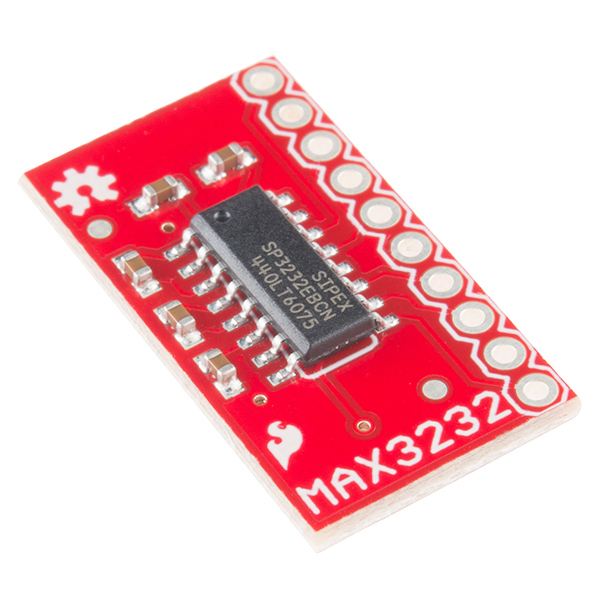
The 'must have' IC for TTL/CMOS projects finally has its own breakout board! This is the RS232 converter IC that is capable of running at 3V and communicating with 5V logic.
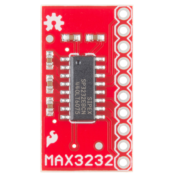
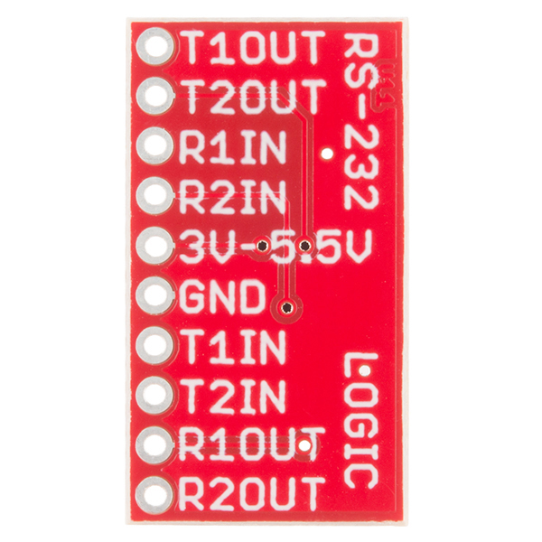
We've taken the SOIC package MAX3232 and broken out all the pins you need to set up your RS232 to TTL connection. We've also included the necessary 0.1uF charge pump capacitors. Also remember that because the MAX3232 operates at a broader voltage range than the 232 (3 - 5.5V) you can use this on both your 3.3 and 5V projects!
- Schematic
- Eagle Files
- Fritzing Part
- Datasheet (3232EB)
- GitHub (Design Files)
SparkFun Transceiver Breakout - MAX3232 Product Help and Resources
Example Hookup
For an example hookup, see this diagram.
Core Skill: Soldering
This skill defines how difficult the soldering is on a particular product. It might be a couple simple solder joints, or require special reflow tools.
Skill Level: Noob - Some basic soldering is required, but it is limited to a just a few pins, basic through-hole soldering, and couple (if any) polarized components. A basic soldering iron is all you should need.
See all skill levels
Core Skill: Programming
If a board needs code or communicates somehow, you're going to need to know how to program or interface with it. The programming skill is all about communication and code.
Skill Level: Rookie - You will need a better fundamental understand of what code is, and how it works. You will be using beginner-level software and development tools like Arduino. You will be dealing directly with code, but numerous examples and libraries are available. Sensors or shields will communicate with serial or TTL.
See all skill levels
Core Skill: Electrical Prototyping
If it requires power, you need to know how much, what all the pins do, and how to hook it up. You may need to reference datasheets, schematics, and know the ins and outs of electronics.
Skill Level: Rookie - You may be required to know a bit more about the component, such as orientation, or how to hook it up, in addition to power requirements. You will need to understand polarized components.
See all skill levels
Comments
Looking for answers to technical questions?
We welcome your comments and suggestions below. However, if you are looking for solutions to technical questions please see our Technical Assistance page.
Customer Reviews
4.5 out of 5
Based on 34 ratings:
2 of 2 found this helpful:
4/5 I'd rather have given it a 5...
I needed this because the device I'm attaching to was RS232 format output only, and the Pi /dev/ttyAMA0 only likes TTL, so this did the trick. Only thing I had hesitation about was that I had to go to Maxim's documentation to figure out the different pinouts, and I'd have rather that info been readily obvious to me on Sparkfun's website, but I couldn't find it.
1 of 1 found this helpful:
Great little tool - Caveat
Great tool, but keep in mind that the behavior is different depending on the direction. I have a RS-232 device trying to get it to 3.3 TTL. To pull that off, you have to route the RS-232 device into the RXIN and the uC out of the RXOUT. I initially had it going into the TXIN and uC out of TXOUT, but that kept logic levels higher than my Vin. Hopefully something that might save a poor uController some day.
5 of 5 found this helpful:
Great product but with poor instructions
Very confusing to get everything hooked up properly. Better documentation would've made this 5 stars. I'm using this to send commands from arduino uno to an RS232C motor indexer/driver
Pinout by my experimentation is as follows: Arduino Tx -> T1IN Arduino Rx -> R1OUT RS232 Indexer Tx -> R1IN RS232 Indexer Rx -> T1OUT
GND and 3-5.5V are as expected
RS-232 driver receiver
Works just like it should. I have used 5 of these and no problems.
Works as advertised
This little board does what I needed and was easy to integrate into my project. The I/O holes all in a line are nice as well as the labels of each hole on the back.
handy little board works great
I realized I needed to add an RS232 driver to an existing circuit board lacking in board space. This little board allowed me to mount it vertically with all the signals accessible on a .1" spacing. It worked like a charm and converts the signals to the proper levels.
Good Product
I needed a quick, simple, economical way to interface a PC's RS-232 port to a PICAXE micro. Worked perfectly, no problems. Great product!
Does the job perfectly in a small package.
Just what I needed to add serial port communications to my +5V project.
Works perfectly!
I had an old homebrew max232 circuit that gave up the smoke and didn't feel like making another. The MAX3232 breakout from Sparkfun worked perfectly as a replacement. I even bought a couple extra for future needs.
Decent quality
I use this on one of the boards I designed. Ebay compatible boards are cheaper but this one usually has good quality. Slightly lowering its price will be nice.
Does the job.
Only wish the labeling listed RS-232 inputs and outputs as an option. Wiring it up is a bit confusing at first. At the very least, on-line documentation should provide common wiring for the device (e.g., RTS, CTS, TxD, and RxD for DTE and DCE).
Great interface between Arduino and RS232
Having a project which tapped into the RS232 line between my Ham Radio and the computer, I needed something which would listen to the commands being sent down the line. This afforded me the perfect form factor to plug into my circuit board and provide the necessary translation. I had a great deal of trouble understanding which line went to the TX line and which went to the RX (I'm a little slow and easily confused!), but once I finally figured it out, everything went fine!
Solid breakout board
This board was easy to work with, perfect for my prototype!
Simple, but important function
Does what it is supposed to do and fairly versatile.
Very handy breakout
This breakout board neatly converts either TTL or 3v3 serial outputs to RS232-level signals and vice versa. This is great when you have a serial port which requires these levels - such as a PC with a serial card or a modem. If you need this conversion this is the board for you. Make sure you have a gended-changer if you need one. Enjoy!
SIPEX SP3232
They are great so far, except they are a bit expensive, but they saved us much effort thanks to the enhanced ESD Protection of the SIPEX SP3232.
Works fine
A bit overkill, though. I'd prefer a one-channel version that doesn't take up as much space.
Easy way to get 2 REAL RS232 interfaces on your project.
If you want a quick way to get TTL signals to RS-232 levels, this is a quick and easy way to do it without surface mount solder tools.
Very Usefull
I need to quickly build a board to translate TTL serial into RS232 signals, this was the perfect solution to use on breadboard.
OK for testing and design, but no hot plugging
I used this board to validate a design. Sparkfun is awesome with their opensource content. The board did what I needed it to do, but it burnt up during testing. I read on line some poor reviews of the SIPEX version of this chip. No hot swapping. Make sure you power off before moving jummper wires around.
Great boards
Much better that the cheap clones sold on eBay and other sites
These are great
I am a hobbyist and have used these a couple times and they are great. They take up less board space and allow quick hookup for rs232 comms to a micro. thank you Sparkfun. BOB's are great for prototyping or even for final design.
works great
Easy to use.
Very smart device
This is exactly what you need if you are trying to make your own RS232 interface. It doesn't get any easier than the MAX3232 board. Thanks
Gave my ATmega8-16PU I/O support like a computer terminal!
I'd read the reviews and thus followed their advice to use the clear example connections in the Sipex's datasheet. Nevertheless, I had plenty of serial data corruption until I solved my timing issues by expanding upon the partial source code provided and building it myself (instead of relying on a pre-built .hex file). Now the ATmega8-16PU is running at 8MHz and its RS-232 I/O is 115200 BAUD 8N1 which is working great (with flow control turned off) in GNU/Linux's "minicom -s". My first foray into RS-232 interfacing can finally be considered a resounding success! A proof-of-operation stepping-stone, before I had the timing right, was in shorting the TTL-side pins (T1IN to R1OUT) to test loopback worked.
Just the ticket for configuring Bluetooth modules
I needed a 3.3v TTL to RS232 converter to talk to my HC-06 Bluetooth modules in order to use the AT commands. Worked great.
Nice little board, easy to use
I just needed to translate from 3.3 to rs-232 levels. This little board is just the trick. Easy to use and the connections are well labeled. I like that all of the connections are on the same edge on 0.100 centers. I soldered a right angle header in those holes and mounted it like a SIP.
must have when working with older devices
Works great, just like you'd expect a MAX3232 to be. Would have 5 stars if it could plug into the programming headder on the Arduino Pros and have holes for the terminal side DB9 connector along with headders for the RX2 and TX2. But this is good, much handier than stuffing DIP in breadboard along with the caps.
Very nice breakout
it works very good, nice design.


I connect my MCU (3.3 V) to an RS232 device. I got the right output voltage on each side. And there is communication between them. But I did not get the right answer from the RS232 device. Is the board broken? The code works well with a previous self-made max3232 board with the maxim max3232 Do I need to add a resistor to the pins T1IN and T2IN on the board? Since we have the resistors on the self-made board
Hi there, it sounds like you are looking for technical assistance. Please use the link in the banner above, to get started with posting a topic in our forums. Our technical support team will do their best to assist you.
Is there a Fritzing component for this board?
I have a question and I would like to know your opinion about it.
I want to connect my MCU whose pins are only tolerant to 3.3v to an RS-232 device.
From what I understand, I could connect my MCU (3.3v logic) to the driver pins, but feed (Vcc) the driver to 5.0v, right? Even if I feed the drive to 5.0v can I connect it to the MCU (3.3v logic)?
The datasheet says on page 8: "This series is ideal for + 3.3V-only systems, mixed + 3.3V to + 5.5V systems, or + 5.0V-only systems that require true RS-232 performance. "
But I can not understand how the driver can distinguish if the output to the MCU should be 5v or 3.3v.
Thanks for your help ... and I apologize in advance, if it is obvious. :S
You can power the MAX3232 from 3.3v, so just feed that into the Vcc pin, and it will work. The RS232 output will still be ±5v even powered off 3.3v
I got a handful of these recently. They appeared to be working correctly. I am using one to boost a ttl signal to rs232 and then another to bring it back to ttl levels. However, when I scoped the rs232 output (T1OUT) The signal is +-5V. Exactly the same as the signal going to the device (T1IN). Shouldn't it be +-13.2v as the datasheet states? What are other people seeing?
+/-13.2V is the absolute maximum on the output pins, not the expected output. The expected output is +/-5V, which it sounds like you're getting. See "Driver Outputs" section of the Electrical Characteristics table, near the bottom of page 2.
I'm looking to use this in a mostly-permanent application, and would like some sort of screw/bolt holes. Is it safe to drill small holes in the corners, approximately where the open source logo, and where the "M" are? There don't appear to be any traces there, just the ground plane copper.
You should be okay to do that; I'd use either nylon screws and standoffs or non-conductive washers (at the very least) because you'll probably expose copper doing that and you don't want to accidentally chassis bond your ground plane.
I have a few of these boards to mod an existing circuit, the boards are getting pretty hot to the point of being uncomfortable to touch. Any previous instances of this happening and if so is there a fix?
That is extremely unusual. Triple check your connections and make sure that you're not dumping a TX to a TX and causing bus contention, or possibly exceeding your supply voltage rules. If not, contact tech support; maybe a bad batch went out? It's unlikely, but possible.
Can this handle 12V RS232 signals?
yes; it also handles the signal inversion and level shifting needed for true RS232 signals.
Take this and add an SC16IS740/50/60 (an I2C-based UART), or equivalent, on the back and you got a neat little board to add RS232 to an I2C bus.
Alright, I'll try it, but if it doesn't work you're going to have to come to my house and fix it! (Thanks for a great suggestion!)
Any chance we will ever see a board like this with a DB9 and a MAX3232 on board? Just about every time I use RS232 there is a DB9 connector somewhere, either on the PC or a device.
Very Cool! Now, if you could put LEDs on it for status, it would be perfect!
Im looking at using one of these (and an arduino pro Mini) to make a button panel in my wall, which when i push a button sends a string done the RS232 to a controller. can anyone recommend what cable length would be suitable for the rs232 comms? (what would be a max safe distance) assuming i am using a two core screened cable. the whole unit will be powered via 12V on a separate cable
OMG - what a HUGE PITA the naming convention used on the pins of this board!! It is a real nightmare to try and remember that R1IN is RS232 but T1IN is TTL/5V!
I hope you redo this board some day and come up with a more intuitive pin-naming convention. Serial comms is always confusing (who is sending, who is receiving.. ) - Also it would be really super if you brought out the Enable pin as well.
You should add more holes for ground connections. If you use this for two RS-232 connections you need to connect 3 wires to one hole. Having 3 holes would make it much easier to wire.
Be aware that the datasheet says "The drivers are inverting level transmitters that convert TTL or CMOS logic levels to ± 5.0V EIA/TIA-232 levels inverted relative to the in- put logic levels.". So, it wont work in serial communication between RS232-ttl (like in beaglebone(3.3V) with arduino(5V) or raspberrypi(3.3v) with arduino). Since it inverts the bits, it will also invert the start and stop bits, messing up with the serial protocol.
You're reading a whole lot into that single sentence from the datasheet, and making some reasoning about the RS232 protocol that I'm having trouble following. As for Beaglebone, check this serial cape that uses the same driver chip, with essentially the same circuit from the datasheet's 'Typical Operating Circuits' section:
http://elinux.org/BeagleBone_TTL-RS232_Micro_Cape
Most devices do let you play with the start and stop bits if you have the board already. If not you really just need a logic level converter to go from the 5V Arduino to the SBC (the Arduino will read the 3.3V just fine).
Is it possible to program the Arduino Pro Mini through this device?
My project interfaces with anther device via RS232 so I have the MAX to communicate with the other device. Instead of taking my project apart to reprogram it I would like to simply use the external interface. I bought another MAX and hooked an FTDI USB programmer to it. I can see my serial traffic when the project is running but for some reason the Pro Mini doesn't respond to the Arduino IDE.
Any suggestions?
You should be able to program through it, although I've never tried it.
Start the upload as normal in the Arduino IDE, then push the reset button on the Pro Mini. When the Pro Mini comes out of reset, it will briefly enter the bootloader, and the upload should proceed as normal.
No guarantees, YMMV, etc.
Will this work out-of-the-box with an Arduino Due (3.3v) device? I don't want to end up frying my SAM3X8E....
Yes, the voltage range is 3V-5.5V.
What is the logic level? is it 3v or 5v? Does it change depending on the supply voltage?
Am I reading the schematic correctly? Is this, somehow, dual channel? I'm considering making a 'serial spy' that listens to both the Rx and Tx lines of a cable, and transmits them out another converter to a computer, so you can see how the devices are communicating. Dual channel (being able to have two Rx lines) would be awesome.
Yup, it's dual channel, so sniffing RX and TX and dumping that into, say, an FTDI Basic board would be a terrific application for this.
During normal operation how much current does this chip draws? I'm I reading correct from the datasheet that it only takes 1 microAmp?
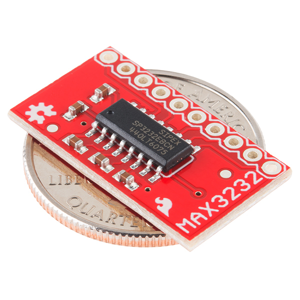
What are the dimensions of this board?
+1
Does this let me put an RS232 input onto my arduino?
That's what I was going to use this board for. I have to run twisted paired signals about 12 feet.
Yes. You put Arduino RX to R1IN, Arduino TX to R1OUT, serial devices TX to R1IN, RX to T1OUT. Then add ground and voltage. Hope this helps.
I only found success by experimentation, and very definitely ended up as follows: Arduino TX > MAX T1IN Arduino RX > MAX R1OUT MAX T1OUT > Serial TX (Pin 2) MAX R1IN > Serial RX (Pin 3)
This using a Mega 2560, FWIW.
Shouldn't serial devices TX not go onto T1IN?
This was needed a longgg time ago. Thanks for finally getting around to make it! 3v3 projects will now be able to communicate to the outside world.