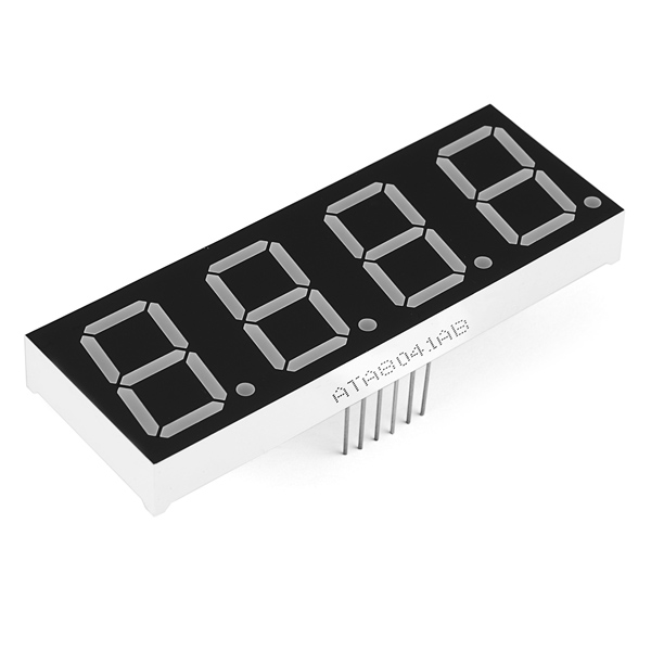
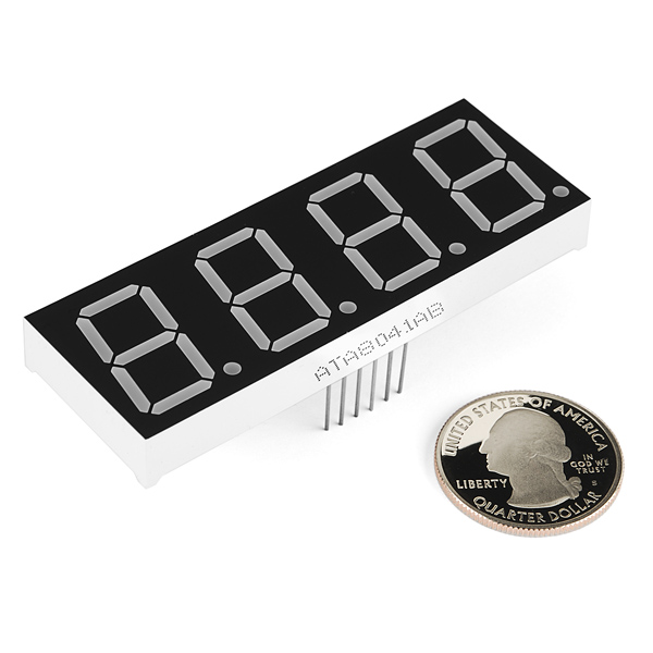
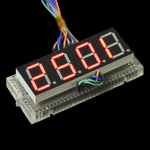
For a long time we've had small 7-segment displays and *huge *7-segment displays, but now we finally have something in between. These 20mm 4-digit 7-segment displays are big enough to see from a distance but not so big that you'd have trouble finding an enclosure for them.
These common-cathode displays feature 4 x 7-segment digits and one decimal point per digit. The LEDs have a forward voltage of 1.9VDC and a max forward current of 20mA.
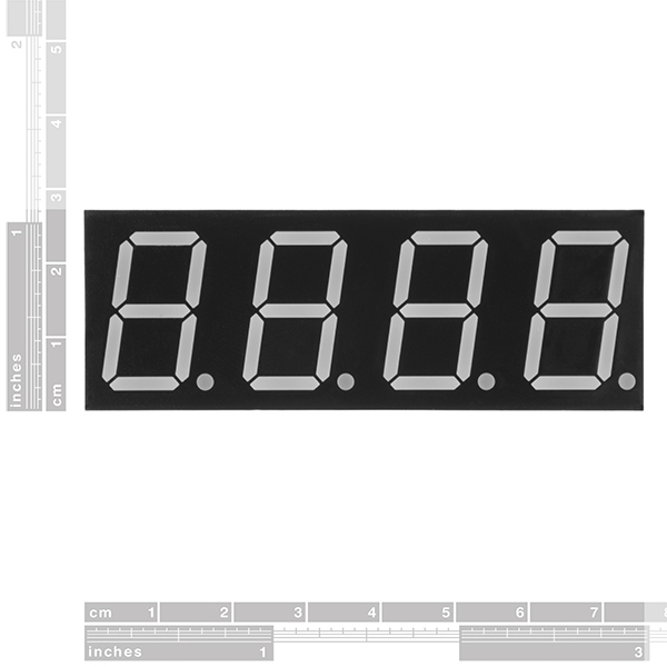
- 71.6 x 25.7mm
7-Segment Display - 20mm (Red) Product Help and Resources
Using OpenSegment
April 1, 2013
How to hook up and use the OpenSegment display shield. The OpenSegment is the big brother to the Serial 7-Segment Display. They run on the same firmware, however the OpenSegment is about twice as big.
Using the Serial 7-Segment Display
August 13, 2013
How to quickly and easily set up the Serial 7-Segment Display and the Serial 7-Segment Display Shield.
Core Skill: Electrical Prototyping
If it requires power, you need to know how much, what all the pins do, and how to hook it up. You may need to reference datasheets, schematics, and know the ins and outs of electronics.
Skill Level: Competent - You will be required to reference a datasheet or schematic to know how to use a component. Your knowledge of a datasheet will only require basic features like power requirements, pinouts, or communications type. Also, you may need a power supply that?s greater than 12V or more than 1A worth of current.
See all skill levels
Comments
Looking for answers to technical questions?
We welcome your comments and suggestions below. However, if you are looking for solutions to technical questions please see our Technical Assistance page.
Customer Reviews
4.5 out of 5
Based on 2 ratings:
1 of 1 found this helpful:
Good value for a basic 7-Segment Display
This relatively inexpensive display works well after you know how it works. To that end, I published a basic hookup guide on hackster.io:
https://www.hackster.io/meljr/sparkfun-com-11408-4-digit-7-segment-display-hookup-guide-4b4d9e
Goodie
Big and bright 7-segment display.

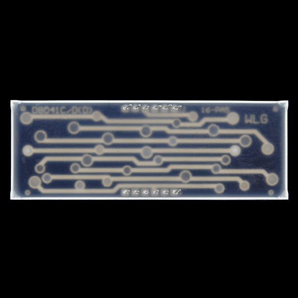
Will not sit flush on standard protoboard: while the pins have standard spacing along the length of the rows, the rows are not spaced on a multiple of one-tenth-inch (data sheet says 22mm, and they may actually be so spaced). However, the long leads allow some flex so it works fine in a breadboard/perfboard/protoboard, just not flush mounted.
Nice bright leds. Digit selection on ground, segment selection on Vcc. (Not saying anything about "cathode" or "anode" because I get them mixed up ever since a lecture about cats and cations in a chem class.)
I wrote a library for this. The repo also includes a schema how to connect this display.
see https://github.com/renes/fourDigitLCDDisplay
Thanks for this, it made learning this much easier!
Has anyone figured out the pin layout for controlling this display?
All the segments share the same pins, with the exception of the cathode. To display a single digit, pull that cathode high, with all the other cathodes low. to display all the digits, cycle through the cathodes while changing the pins to match.
Still no data sheet or pin layout?
All 4 digits when on at the same time are a bit dim when driving with just the Arduino Uno.
I wrote a library for this. The repo also includes a schema how to connect this display.
see https://github.com/renes/fourDigitLCDDisplay
Really great display; plenty bright and feels robust. Managed to get it working well with a MAX7219CNG using a 47k ohm resistor and two decoupling capacitors (0.1uf & 10uf). Admittedly, my greatest obstacle was the enigmatic datasheet which proved irksome to say the least...
which pin is pin #1? I am using 4 - 74ls47 chips to control the display of each digit of this product's display. The datasheet doesn't explain which pin is power and ground. Thanks for your help.
If you have the display facing you with the decimal points at the bottom, then pin 1 is the left-most pin on the bottom row of pins..just as the datasheet indicates :)
There's more than 1 power and more than 1 ground pin.. that is to say, each digit on this display has its own ground pin (the common cathode), and then there's 8 'power' pins (the anodes) for each segment.
( The above applies if this display is common cathode as per the description - swap anode/cathode if it's common anode, as per Member #470208's comment. )
The 74ls47 you're using is intended for a single digit - you can still use one with this display to drive the segments, but you'll need something else to select which digit is 'active'.
Arg, this is NOT common cathode, it is common anode. As in, I hook up pin 6 (one of the common pins) to +5V VCC and hook up pin 1 to GND via a resistor (one of the segment pins) and the segment lights up. Inverting that wiring and the segment does not light up. When hooking this up to a MAX7219CNG chip, all the segments are lit regardless of display test mode, etc (a common problem when hooking up a MAX7219CNG to a common anode display).
Is there an Eagle library for this? Can't seem to find it in the normal Sparkfun lib on git hub. Will make it if I need to, but would rather just use something that is already there.
Assuming the datasheet linked to is correct, the pinout matches the part 7-SEGMENT-4DIGIT-COUNTER-PTH in SparkFun-Displays.lbr .
Hi, where can i find and download SparkFun-Displays.lbr? I have the same problem, can't find the library 4 digits 7 segment in eagle.
SparkFun's libraries are currently hosted at GitHub. Hopefully the following link will be around for years to come and always point to the correct location:
sparkfun.com/static/eagle/
Hi, thanks! I find it. :) But where i open the library in eagle, it say "Invalid datain file C.....bla bla bla" So, i still can't open the library. What should i do?
It's a library made for Eagle v6 (the file was authored in 6.5).
If you are using Eagle v6, make sure you downloaded the actual library file (it's often best to just click on the "Download ZIP" button at the repository in github), and not e.g. an html page :)
If you're still using version 5... well I can at least highly recommend upgrading, but if you can't: you'll need it backported :) I no longer have version 5 installed to check, so hopefully this works. Below is a link (people from the future: that link may be dead - sorry) that will take you to a bunch of text. Scroll down on the page to find a form element that has the same text that you can easily copy. Paste that into a file, save it as 'somename.scr'. Then in Eagle, start a new library, enter the command 'script', browse to the location of 'somename.scr', and let it run. It will then ask you where to save the library file - pick any location you like, and you should have a library with exactly 1 device/symbol/package: the 7-segment 4-digit display. I think I noted elsewhere (and I see user 'hads' below notes it as well) that this product is actually a bit wider, so you may want to tweak that before you include it in any designs.
http://pastebin.com/4k6v2Kiv
Oh God! You're right Kamiquasi. I still have version 5. I'll upgrade it soon. Hopefully the library running well after that. Thank you so much for complete explanation. :)
Just a heads up that the silkscreen outline for this in the Eagle library appears to be about 7mm too narrow.
Now what we need is these larger displays with the serial/arduino interface like the smaller COM-11441 displays.
I found the datasheet through another website. Half of it's in Chinese, but it's better than nothing.
http://dlnmh9ip6v2uc.cloudfront.net/datasheets/Components/LED/ATA%20datasheet%20red%20ATA8041BR.pdf
This datasheet states that the display is common anode. But according to my test it is common cathode.