6-Pin Chassis Connector - Panel Mount (male and female)
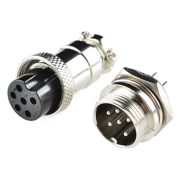
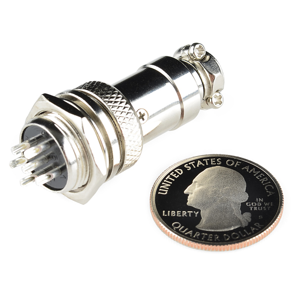
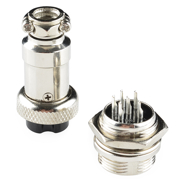
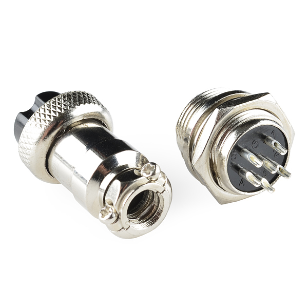
This 6-pin connector and plug set is great when you need to create a robust connection for signal or power. This product consists of two separate parts, the panel-mount jack and the mating plug. The plug has a ring which screws to the panel-mount connector ensuring a solid connection that won't pull off.
The connector uses 6 solder-cup connections for easy wiring. The panel-mount side mounts in a 15.5mm hole with the aid of a lock-washer and nut (both included). The jack uses solder-cup terminals as well and comes apart for easy assembly. It even has a strain relief clamp on the end which clamps down to 5mm for a sturdy connection. Pins are clearly labeled on both jack and connector.
6-Pin Chassis Connector - Panel Mount (male and female) Product Help and Resources
Core Skill: Soldering
This skill defines how difficult the soldering is on a particular product. It might be a couple simple solder joints, or require special reflow tools.
Skill Level: Rookie - The number of pins increases, and you will have to determine polarity of components and some of the components might be a bit trickier or close together. You might need solder wick or flux.
See all skill levels
Comments
Looking for answers to technical questions?
We welcome your comments and suggestions below. However, if you are looking for solutions to technical questions please see our Technical Assistance page.
Customer Reviews
No reviews yet.


These are similar to the Philmore imported Ham and CB mic connectors. Philmore datek is pretty much inactive http://www.philmore-datak.com/
http://www.philmore-datak.com/mc/Page%2054.pdf These sparkfunk are a bit different
http://www.intertexelectronics.com/Philmore-61-603-3-Pin-In-Line-Female-Mobile-Connector-P10327.aspx
Note https://www.calcentron.com/Pages/philmore/philmore_multi-pin_mobile_connectors.php
"Hard to find"
... from a bygone era.
"10-4 good buddy..."
Currently only 8 in stock - will there be more shortly?
What is the max AWG wire size recommended for these connectors?
Unfortunately the data sheet was captured at such low resolution that the dimensions cannot be read.
How much current can these handle? They look perfect for connecting my stepper motors to my control box for my CNC router.
Not sure if it still matters, but anyone who might be wondering as well, the datasheet appears to show 5A max. I was only able to decipher "electric current" from the row with all 5's. Also, the pin sizes appear to be 1.5mm, the nearest AWG wire size safely allows 4.7A for power transmission, so it seems likely the datasheet is saying 5A. Anyone who can read Chinese might be able to confirm.
I would say prob no more than 10A per pin (that is the upper limit that I have pushed the 4 contact variant of that. Note as the pin count increases the diameter of the pins reduces.
I would suggest you give it ago but have a IR temperature gun and keep tabs on the temperature until your sure
edit: Found this connector on another site and the datasheet states no more than 1A per pin and 48 volts
Not sure if I am aloud to post this link, SF feel free to rendict it if need be http://www.farnell.com/datasheets/1461069.pdf
I am hoping you guys can get more of these bad boys in :D they even have them in 90° variants which is really bloody cool :)
A general question on a wiring setup with these connectors - if I am connecting to multiple devices (say small motors), where each one needs a V+ and ground (all go to a common ground), is it okay to make one pin on the connector connected to ground and the rest of the pins the V+ output? And then tie all the motor grounds together and go to the ground pin on the connector?
Could Sparkfun please provide a datasheet that is written (or at least mostly translated) into English?
Specs elsewhere list this as an M16x1 thread on the panel mount side. The clearance hole for this is described on tap charts as 18.0mm or 45/64". The retaining ring (on the connector's panel top side) looks like it's either 18.5mm or 19.0mm, so drilling a 16-17mm may make for a more secure fit. I have these on order and will take calipers to them when they arrive.
For more information on these plugs, they are GX16 6pin, which seem to be the same thing as CBC 6 connectors.
Any chance of getting these bad boys in 8 way configuration? My Alinco radio has one and it would be nice to be able to readily get my hands on one of these for when I get into packet radio
Really basic question--where would one find appropriate wire for this connector?
I think you can use something like 6 conductor trailer cable - It's fairly high gauge so should fit snugly.
What is the size of the hole needed in the chassis? I'm making the 'cut' patterns for the back panel. I want to cut all the aluminum chassis panels on my CNC machine. Thanks
Is it possible to offer these connectors with the genders reversed? In other words, have the panel mount jack be female and the mating plug be male?
Like gdgt mentioned, these look great for connecting stepper motors to a CNC mill control box I'm designing, but I generally prefer to have female jacks on the box and have the plugs be male, like plugging an applicance into 120V wall outlets. Maybe I'm thinking about it wrong, but if I'm powering the steppers with a 28V supply (using a current limiting resistor), I assume the connectors would have 28V on them. Having female pins seems safer to me as there's no male pins sticking out waiting to be shorted to something (or someone, me?) by accident.
You're absolutely correct that best engineering practice is to have the "hot" side of a plug on the female / recessed side. These may have been designed to be used as a power input, where the power is coming in on the cable end. We'll look into carrying the opposite version. Thanks for the great feedback!
Awesome! How long would it take to see if they're available, and if so how long would it take to get them in the store? I'm almost done with my design and will be ordering parts soon-ish. Was going to use DB9 connectors, but the holes for these would be much easier for me to machine. If it's on the order of weeks, I could probably wait. If it's on the order of months, I might just go with my original idea. Or perhaps just get these for now if they'd be the same size as the reversed gender type. I've looked around the web for the reverse of these, but haven't found the same type of pins and connectors... Thanks for the reply!
Product cycles here can take a few months, so it's not likely to happen fast (sorry!).
Since you'll (hopefully) never be hot-plugging stepper motors into your controller, these should work fine for your application.
That's a good point! Thanks!
For what it's worth, this appears to be the exact connector on my Xytronic soldering station.
I have a DC digital Hakko soldering iron controller. (This one. http://letsmakerobots.com/node/32675) I would love to mod the board into a project box, looks like I could plug my Hakko iron into one of these for a nice solid connector on the box. These look like a DIN 45322 (60'Deg pin spacing), am I correct?
looks like the mic connector used on some ham radios.
Aren't these known as 6-pin DIN connectors? (DIN for the German standards body Deutsches Institut für Normung).
To my knowledge they are called "Microphone connectors" by some places. Both of my Alinco rigs have connectors simular to these (except its 8 ways), its also used on some CB radios, the old AM CB I have uses a 4 way connector.
edit: Further to my previous post, https://www.sparkfun.com/products/9536 is a DIN connector
Are they water proof or water resist? Suitable for outdoor use?
I love these connectors, but they're decidedly not even water resistant. Made the mistake of using a pair on my R/C boat - not good. You could probably mod them to be slightly resistant by adding some grease, but I wouldn't go that route unless you really need to.
Hey that's a great price on a panel mount microphone jack and plug. I've been looking for something better than the usual 4 pin connectors for use in an amateur radio transceiver project.