Papilio VGA Wing
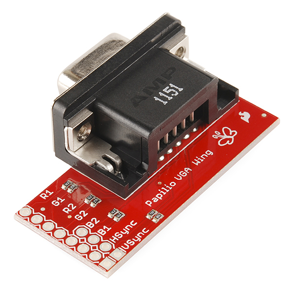
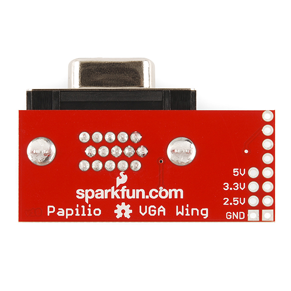
Do you dream of basking in the glow of 8-Bit VGA? Dream no longer, my friend. The Papilio VGA Wing has all of the hardware you need to add a VGA output to your next Papilio project.
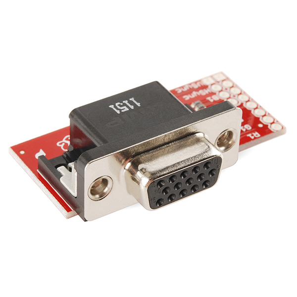
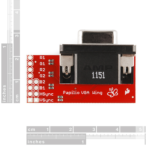
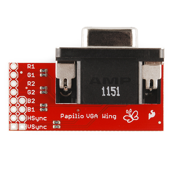
VGA is great because it's fairly universal, grab any old computer monitor and you've got yourself a full-color display to output graphics, text or just amorphous clouds of colorful fluff. The VGA Wing is comprised of a standard 15-pin High Density connector which is connected via resistor voltage dividers to a row of male pin headers which will plug directly into your Papilio FPGA development board.
VGA graphics can be generated by ZPUino, a supercharged Arduino-compatible soft-processor, using the VGA Library!
Note: This product is a collaboration with Jack Gasset. A portion of each sales goes back to him for product support and continued development.
- Add VGA graphics capability to your Papilio project
- Voltage Divider design allows for fast response times
- 8-Bit Color!
Papilio VGA Wing Product Help and Resources
Core Skill: Soldering
This skill defines how difficult the soldering is on a particular product. It might be a couple simple solder joints, or require special reflow tools.
Skill Level: Noob - Some basic soldering is required, but it is limited to a just a few pins, basic through-hole soldering, and couple (if any) polarized components. A basic soldering iron is all you should need.
See all skill levels
Core Skill: Electrical Prototyping
If it requires power, you need to know how much, what all the pins do, and how to hook it up. You may need to reference datasheets, schematics, and know the ins and outs of electronics.
Skill Level: Rookie - You may be required to know a bit more about the component, such as orientation, or how to hook it up, in addition to power requirements. You will need to understand polarized components.
See all skill levels
Comments
Looking for answers to technical questions?
We welcome your comments and suggestions below. However, if you are looking for solutions to technical questions please see our Technical Assistance page.
Customer Reviews
No reviews yet.

How do you get 8-bit color out of it? I would think you could get 3x3x3 = 27 colors ? i.e. for any color pin you could drive the final voltage to 0, 1/2, or 1x supply.
Not sure where you get 3x3x3 from? Look at the schematic, 2 bits per colour. 2^3 = 8 bits of colour info.
You should read about vga. This is simply a vga connector breakout board with onboard resistors. to get color you can pwm the red/green/blue pins with an fpga/microcontroller ( as long as you pwm faster than vga clock frequency). Quality vga controllers are actual digital-to-analog chips. They usually have 10 digitally controllable pins per color.
I think rbarris has the right math. Looking at the schematics, you have 3x3x3 = 27 colors (could be 4x4x4 if they were not all 270). I think they mean 8-pin. At any rate, this board doesn't seem to provide 8 bit color in the sense someone would expect, 256 colors controlled by 8 bits; at least by the schematics. Perhaps something like 3 bits x 3 bits x 2 bits (8 x 8 x 4 comibined.) I guess you could pulse it, and set up some sort of capacitor to smooth out the pulses, but the board doesn't have that, nor a place to inject it. If it expected that, it shouldn't need the 3 states per color it has now, 2 would have done it, reducing the resistors from 6 to 3. So I am at a loss how they call it 8 bit. The link to the web site shows a 3 bit interface, which this has just a little more power than, but not 8 bit, nor any demo on that web page or library showing 8 bit.
From the Papilio vga library:
In summary, the color resolution supported is 8-bit (VGA.H). 3-bits Red 3-bits Green 2-bits Blue
The actual VGA soft-core, termed 'Hyperion' utilizes a digital to analog (soft-core design) called 'sigma-delta DAC' to simulate analog voltages (fast pulse-width modulation).
http://www.xilinx.com/support/documentation/application_notes/xapp154.pdf
The actual sigma-delta DAC used is only 2-bits wide. But now you have 2-bits analog on Red0 and 2-bits analog on Red1. The VGA.H library restricts this to only 3-bits Red (same for Green). The VGA.H also restricts the Blue to only 2 bits (for papilio one). I believe there is full 4x4x4 with other boards (from what I can see from the VGA library).
Some of my information may be inaccurate regarding the sigma-delta component, as I've only JUST read about it. Below is a link to the actual HDL for Hyperion.
https://github.com/GadgetFactory/ZPUino-HDL/blob/master/zpu/hdl/zpuino/boards/papilio_one/s3e500/variants/hyperion-logicstart-megawing/papilio_one_top.vhd
Would this be suitable for non-papilio projects? I happen to have one, but have been looking for a good VGA breakout board for another project. The schematic looks fairly simple. Not sure why 3.3V is "connected" rather than just being left blank
This could be used with non-papilio projects (ie. Arduino, TI Launchpads, insert any microcontroller or FPGA, etc). I was looking for something like this months ago and ended up doing my own.
would like to add that VersaModule.com has one that allows you to use any micro. What is neat about this in my opinion is that you treat it just like you would and LCD and it handles the VGA timing for you.
If you are using a much less complex micro, use this suggestion above ^ Doing proper timing with something like...arduino will take up most of the processing power.
Or better yet(never used it, but it looks good): https://www.sparkfun.com/products/11767