SparkFun OpenSegment Serial Display - 20mm (White)
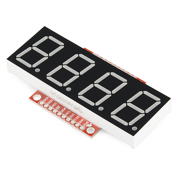
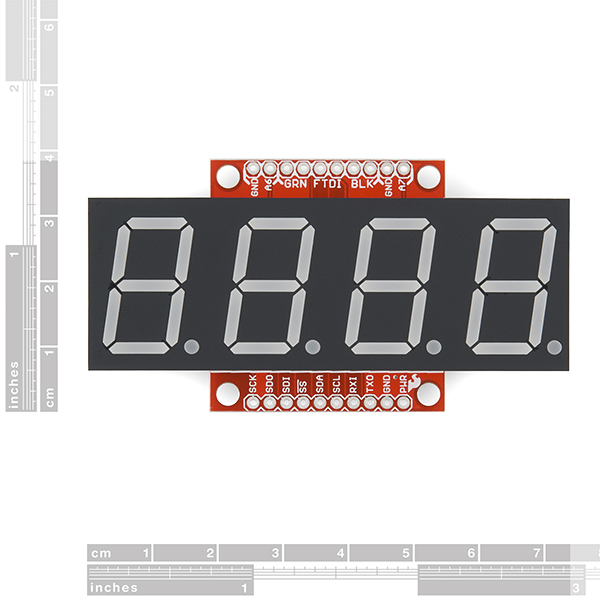
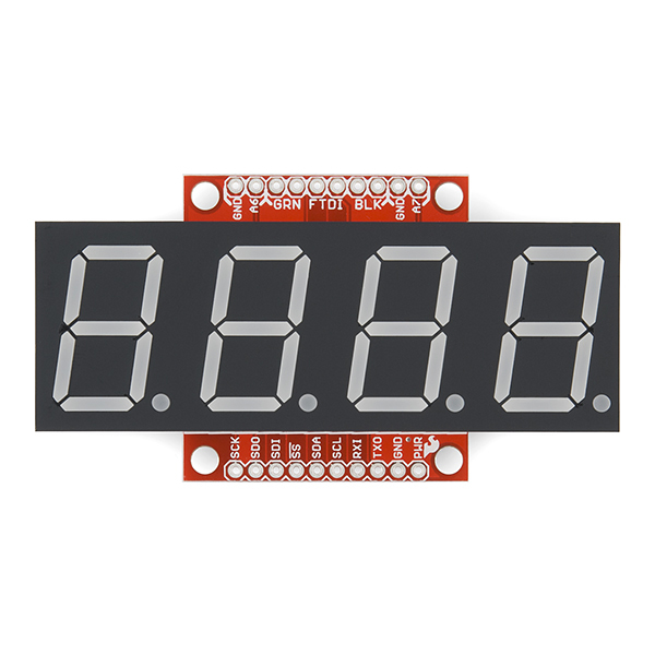
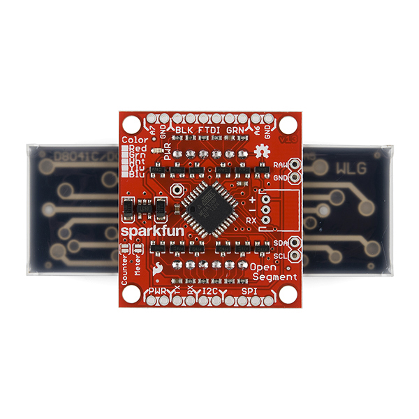
OpenSegment makes it easy to add a large 7-segment display to your project. Because larger 7-segment displays pull more power than a microcontroller is able to drive directly, the OpenSegment has 8 PNP and 4 NPN transistors in order to drive the segments at their maximum brightness!
The on-board ATmega328 receives data over multiple digital interfaces (such as TWI, UART and SPI) and does all the PWM and upkeep of the display so your main controller doesn't have to. There are even two built-in functions that can be activated with solder jumpers. The counter function simply counts up or down, incrementing when you pull down SDO and decrementing when you pull down SDI. The meter function gives you a voltage read-out of the ADC!
OpenSegment runs at 5V and uses a standard FTDI connection for programming. The board is pre-flashed with a bootloader compatible with the Arduino Pro Mini @ 8MHz setting under the Arduino IDE. This firmware is an updated version of the Serial 7-Segment firmware designed to run on both devices. The commands will be largely the same except, of course, that this display only has decimals and no colon. See the datasheet for the Serial 7-Segment below to get an idea of the serial command set.
- On-board Transistors Allow Display to Run at Full Brightness
- Serial Commands Available to Adjust Brightness, Baud Rate, and I2C Address
- Individual Control for Digits and Decimal Points
- Arduino Compatible with FTDI Header
- Built-in Meter and Counter functions
SparkFun OpenSegment Serial Display - 20mm (White) Product Help and Resources
Core Skill: Soldering
This skill defines how difficult the soldering is on a particular product. It might be a couple simple solder joints, or require special reflow tools.
Skill Level: Noob - Some basic soldering is required, but it is limited to a just a few pins, basic through-hole soldering, and couple (if any) polarized components. A basic soldering iron is all you should need.
See all skill levels
Core Skill: Programming
If a board needs code or communicates somehow, you're going to need to know how to program or interface with it. The programming skill is all about communication and code.
Skill Level: Rookie - You will need a better fundamental understand of what code is, and how it works. You will be using beginner-level software and development tools like Arduino. You will be dealing directly with code, but numerous examples and libraries are available. Sensors or shields will communicate with serial or TTL.
See all skill levels
Core Skill: Electrical Prototyping
If it requires power, you need to know how much, what all the pins do, and how to hook it up. You may need to reference datasheets, schematics, and know the ins and outs of electronics.
Skill Level: Noob - You don't need to reference a datasheet, but you will need to know basic power requirements.
See all skill levels
Comments
Looking for answers to technical questions?
We welcome your comments and suggestions below. However, if you are looking for solutions to technical questions please see our Technical Assistance page.
Customer Reviews
No reviews yet.

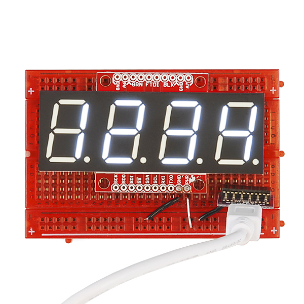
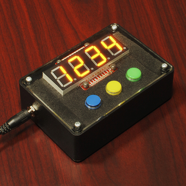
White is so neutral and sexy...i love it.
Nice product with multiple features and good design! Now we are waiting LASER RGB-segments with significantly reduced current draw :)
Resitors are good for equal digit brightness, but additional power dissipation can be expected. If segments should driven without resistors and equal brightness, PWM should be dynamic thus being unique on every digit value while demuxing. This wasn't the case any of the previous revisions. This one is omitted to phenomenom by the resistors, but causes more current to drawn. I think this is still awesome product...
Is anybody else having trouble flashing a custom firmware onto these?
I'm hoping to use it with an RFID reader, and was hoping to alter the firmware to do the talking to the RFID module and add to the serial protocol.
I've got two brand-new boards, and whenever I try to flash them using the code I managed to download, it compiles just fine and I get
avrdud: stk500_recv(): programmer is not responding
The device seems to be rebooting just fine, although it might be skipping the bootloader (or the programming cycle is not catching it). I've tried two devices and two FTDI breakouts, and I've tried swapping the RX/TX pins on the FTDI just in case there's confusion about that.
Any ideas? Is there a baud-rate mismatch or are things just a bit flaky?
If I understand properly, this can be used as an Arduino as is? I'm looking for a display for an anemometer. I've found a sensor that delivers pulses at a rate that varies with wind speed. Seems like I should be able to tie that to SDO, and add a timer function that checks it once a second and resets the count. Could that be done? Assuming that works, what about driving a second one from it via one of the serial interfaces? Thanks, Mike
I bought two of the smaller versions of this display and reprogrammed it via the standard Arduino software to run a custom sketch. I see no reason why any of what you said wouldn't work. I removed the bulk of the Sparkfun code, leaving only the code that drives the LED segments, and added my own code to turn it into a programmable, auto-resetting timer. This required that I re-use most of the IO pins.
I just purchased two of these larger displays for the same project. It appears many of the links in the description are broken, however the schematic link works. I am currently looking at what changes I need to make to allow my code to work on this new display.
I do wish a few of the pads were labeled better.
The questions I have: Which pin on the FTDI breakout is pin '1'? Is the unlabeled pad next to the AVR the reset pin? Can anyone confirm if the RAW and VCC pins are the same?
On the FTDI Breakout you'll find labels 'BLK' and 'GRN'. These are hold overs (color of the wires) from the FTDI cables. These indicators align with the BLK and GRN labeled pins on the OpenSegment.
Let us know if we can answer any other questions.
Sorry about the bad links! I cleaned up the repo where all the files are and it changed the URLs. All the links go to the GitHub repo here. I'm not really sure which pins you are referring to on the board, so I'd recommend double checking in the Eagle files. You can highlight pins on the schematic and have it highlight on the board as well. If you're still having problems with it, please email techsupport@sparkfun.com and they'll be able to help you more in depth than can be done over comments :)
How, exactly, does the meter function work? I soldered the jumper and connected power. I used 2 10K resistors to hold the SD0 and SDI pins high. I connected switches to pull the pins low. However, it does not work as expected. After pressing the buttons quickley and randomly, I got it to display random stuff (000 ) (0F00) ( ). So obviously I am doing something wrong.
EDIT
It seems that SPI will work, if I used it correctly. I have my UNO talking to it via TTL Serial. It is counting from 0001 through 9999 and resets. But the "Counter" function is not working as described:
To be clear: you asked about the 'meter function'. That to me says Analog meter mode where the display shows 0.0V to 5.0V. The remainder of your question seems to be around 'counter mode'. I'm going to assume you're really asking about the counter mode.
When you power up the OpenSegment what do you see on the display? '1234' indicates normal data mode. '0.00.0' is analog meter mode. ' 0' indicates counter mode.
The solder jumpers may not be functioning correctly. Try putting the display into counter mode using the 0x82 mode command (there is example code here).
Oops, I meant counter. It didn't hit me that I put meter.
The display would show "1234" on power up. Now it seems to be working correctly. I have noticed that if I hold RX and TX low (or floating) on power cycle, I need to re-program the display. But if I hold them high, it remains in counter mode.
Thank you. I would have never came across that code otherwise.