SparkFun Solder-able Breadboard - Large
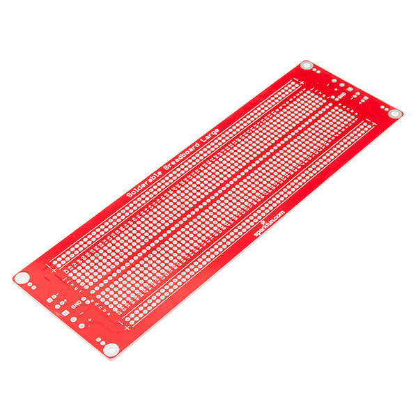
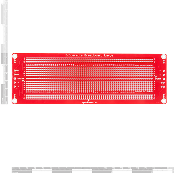
This is the Large SparkFun Solder-able Breadboard. A bare PCB that is the exact size as our full-size breadboard with the same connections to pins and power rails. This board is especially useful for preserving a prototype or experiment you just created on a solderless breadboard by soldering all the pieces in place.
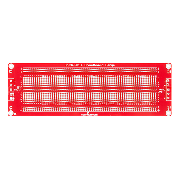
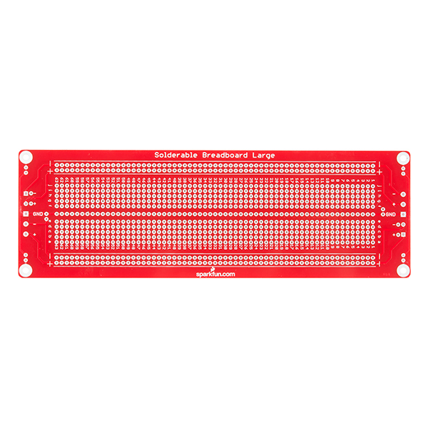
The large solder-able breadboard also includes real estate for screw terminal connectors and a trace down the center gutter for ground.
- Schematic
- Eagle Files
- Hookup Guide
- GitHub (Design Files)
- Product Video
SparkFun Solder-able Breadboard - Large Product Help and Resources
Large Solderable Breadboard Hookup Guide
February 27, 2014
This breadboard has a couple of tricks up it's sleeve!
Core Skill: Soldering
This skill defines how difficult the soldering is on a particular product. It might be a couple simple solder joints, or require special reflow tools.
Skill Level: Rookie - The number of pins increases, and you will have to determine polarity of components and some of the components might be a bit trickier or close together. You might need solder wick or flux.
See all skill levels
Comments
Looking for answers to technical questions?
We welcome your comments and suggestions below. However, if you are looking for solutions to technical questions please see our Technical Assistance page.
Customer Reviews
4.6 out of 5
Based on 5 ratings:
2 of 2 found this helpful:
Worked Exactly as Needed
I made the most complex soldering project that I have ever done, using this breadboard, and it worked great. The only issues came from my own lack of soldering skill, but that is improving some. It took a while to complete the task, because I was working with a new iron and new lead-free solder, so it was a learning experience.
I like that the breadboard has 2 separate power rails, with the option of joining them, which I did not do in this case, because I needed 2 different voltages on those rails.
2 of 2 found this helpful:
Works for what I need it for
The only thing I don't like is that there isn't a project enclosure that fits the board. I would have gladly paid more money and ordered one, had it been available.
Otherwise, works exactly as you'd hope
1 of 1 found this helpful:
Excellent prototyping board
I really like the ground bus down the center channel (I wish the smaller board had that as well) and the provided jumper connections make it very easy to join the power rails on either side without having to use wires. You can also join the central ground bus to the negative rail with another provided jumper, and even optionally ground the mounting holes.
I used this board to create a +12v/-12v power supply for a synthesizer project; the extra ground bus made it a lot easier to deal with two power rails.
1 of 1 found this helpful:
Best large breadboard I've found ....
and this is why. First, I'm building a project with multiple boards and the corner mounting holes make stacking easy. Second, love the fact that you can tie the power rails together. Lastly, its nice to have the ability to use screw terminals at the end of the board to power your project.
I only thing missing, I would have liked is if instead of the screw terminal, I could have used DC power connector.
Breadboard delight
This breadboard is a perfect layout for doing analog or digital projects. You can place any thru hole DIP ICs and have 4 pads on each pin of the ICs for connections. Where IC pins are not used you have 5 pads for circuit nodes. Also great for transistor circuits.


I think it would be awesome if you guys sold enclosures that match the dimensions of these boards with screw holes to match. Maybe make a large enclosure that would be able to mount this board or a few mini breadboards with a standard size Solder-able breadboard. Then have a smaller enclosure that fits just the standard size board. It would make it easier for building and housing projects. Solid black and/or white? Maybe a clear top so we can show off the components? Just a thought.
Hi, I am looking to CAD this part so i can make a 3d printed enclosure for my project. Does anyone have dimensions of the board and mounting holes, also the weight of it? Thanks for your help, sparkfun community.
The board is 7.7" by 2.5".
The mounting holes are 0.1259" in diameter, intended to fit a 4-40 screw. They're set in from the adjacent edges by 0.15" in each dimension.
They weigh less than the minimum resolution on my overprovisioned scale.
Please make the center trace be a dual trace like those along the sides so that power and ground can be brought down the center which most integrated circuits will require to be connected. That way the side runs do not have to be used for that and can be used for other signals. The space exists in the center to do this, so why not use it?
Rev2 should include a partial row of pins offset to support a header row for an Arduino. This will be really awesome.
There is also a Proto Shield for Arduino.
Agreed. I have a few myself. I think that this has advantages over the proto-board for size, less soldering, and jamming stuff in to single holes.
All you have to do is secure this over the breadboard, then once you're done you cover it in copious amounts of glue before soldering!