SparkFun RFM69 Breakout (915MHz)
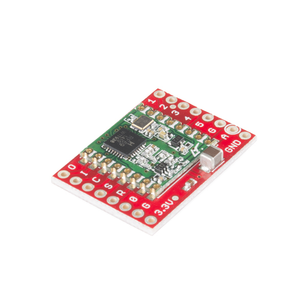
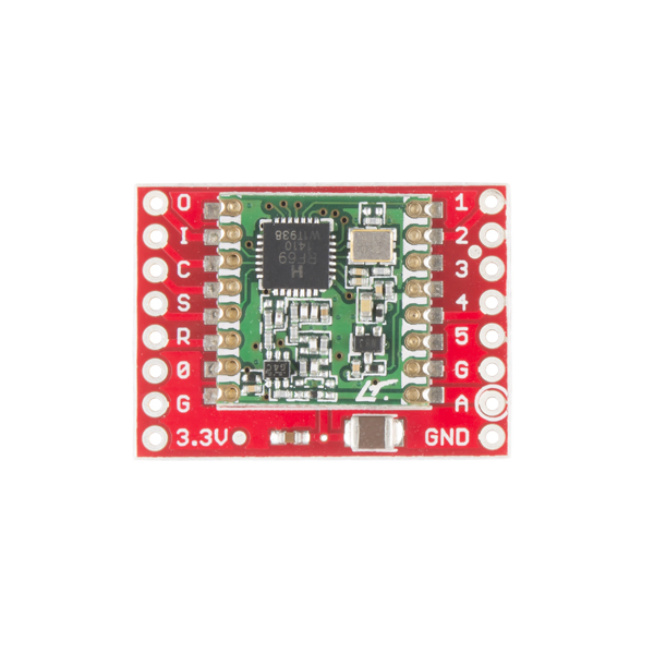
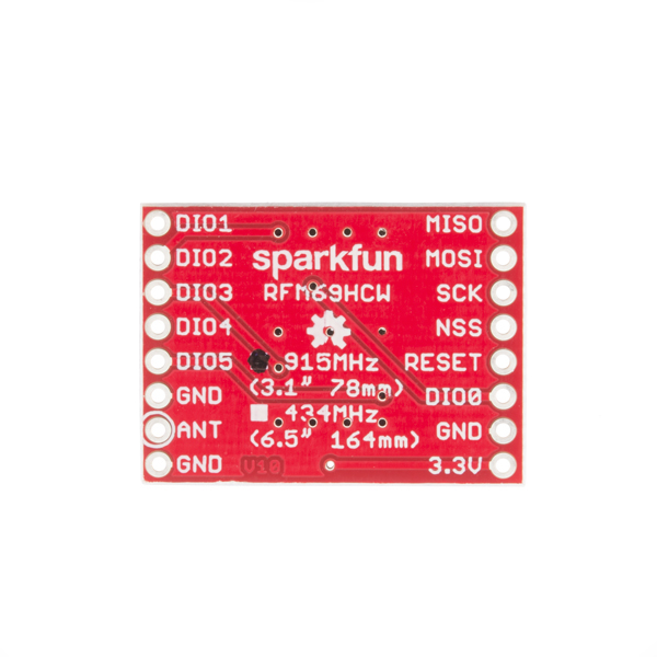
This is the SparkFun RFM69 Breakout, a small piece of tech that breaks out all the pins available on the RFM69HCW module as well as making the transceiver easy to use. The RFM69HCW is an inexpensive and versatile radio module that operates in the unlicensed ISM (Industry, Science and Medicine) radio band. It's perfect for building inexpensive short-range wireless networks of sensors and actuators for home automation, citizen science and more.
This RFM69HCW operates on the 915MHz frequency and is capable of transmitting at up to 100mW and up to 300kbps, but you can change both of those values to fit your application. For example, you can maximize range by increasing the transmit power and reducing the data rate, or you can reduce both for short-range sensor networks that sip battery power. At full power and with simple wire antennas, the RFM69 breakout can get messages from one side of a large office building to the other through numerous internal walls. In open air you can reach 500 meters or more. With more complex antennas and modulation schemes, similar parts have successfully transmitted from space to the ground (by very smart amateur radio enthusiasts; your mileage may vary)!
The RFM69HCW uses an SPI (Serial Peripheral Interface) to communicate with a host microcontroller, and several good Arduino libraries are available. It supports up to 256 networks of 255 nodes per network, features AES encryption to keep your data private, and transmits data packets up to 66 bytes long.
SparkFun sells two versions of the RFM69HCW: this 915MHz version and a 434MHz version. Although the ISM band is license-free, the band itself is different in different areas. Very roughly, 915MHz is for use in the Americas, and the 434MHz version is for use in Europe, Asia and Africa. Check your local regulations for other areas.
- Transmit power: -18dBm (0.016mW) to +20dBm (100mW) in 1dBm steps
- Receive sensitivity: down to -120dBm at 1.2kbps
- Modulation types: FSK GFSK MSK GMSK OOK
- Bit rates (FSK): 1.2kbps to 300kbps
- Voltage range: 1.8V to 3.6V
- Current consumption: 0.1uA sleep, 1.25mA standby, 16mA receive, 130mA transmit (max)
- Encryption: AES 128-bit (optional)
- Packet buffer (FIFO): 66 bytes
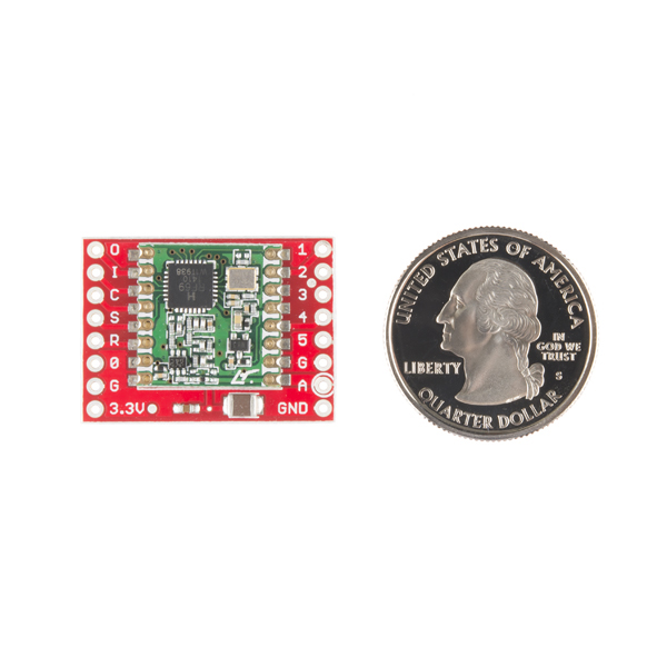
- 0.8" x 1.1"
SparkFun RFM69 Breakout (915MHz) Product Help and Resources
RFM69HCW Hookup Guide
April 29, 2016
The RFM69HCW is an inexpensive transceiver that you can use to create all kinds of wireless projects. This tutorial will help you get started.
How to Build a Remote Kill Switch
May 31, 2016
Learn how to build a wireless controller to kill power when things go... sentient.
SparkFun SAMD21 Pro RF Hookup Guide
October 4, 2018
Using the super blazing, nay blinding, fast SAMD21 whipping clock cycles at 48MHz and the RFM96 module to connect to the Things Network (and other Radio woodles).
Using the RFM69 Breakout with Arduino Yun and Leonardo
If you need to use this with a Yun, (or Leonardo) it can be done. First, connect your SPI pins to the ICSP header. CS in the library on a Yun is not on pin 10. It's on the RX LED. See this picture for a connection diagram. You might want to edit the library code to move CS to a more convenient location.
Core Skill: Soldering
This skill defines how difficult the soldering is on a particular product. It might be a couple simple solder joints, or require special reflow tools.
Skill Level: Noob - Some basic soldering is required, but it is limited to a just a few pins, basic through-hole soldering, and couple (if any) polarized components. A basic soldering iron is all you should need.
See all skill levels
Core Skill: Programming
If a board needs code or communicates somehow, you're going to need to know how to program or interface with it. The programming skill is all about communication and code.
Skill Level: Rookie - You will need a better fundamental understand of what code is, and how it works. You will be using beginner-level software and development tools like Arduino. You will be dealing directly with code, but numerous examples and libraries are available. Sensors or shields will communicate with serial or TTL.
See all skill levels
Core Skill: Electrical Prototyping
If it requires power, you need to know how much, what all the pins do, and how to hook it up. You may need to reference datasheets, schematics, and know the ins and outs of electronics.
Skill Level: Rookie - You may be required to know a bit more about the component, such as orientation, or how to hook it up, in addition to power requirements. You will need to understand polarized components.
See all skill levels
Comments
Looking for answers to technical questions?
We welcome your comments and suggestions below. However, if you are looking for solutions to technical questions please see our Technical Assistance page.
Customer Reviews
4.7 out of 5
Based on 6 ratings:
3 of 3 found this helpful:
Best RF module I ever have worked on
I purchased this module for an industrial project and tested it in very harsh environment with so much electrical noise and it works excellently without dropping a single packet upto 150 meters with normal wired antenna. May be work more than 150 meters with proper physical antenna.
6 of 6 found this helpful:
You can easily connect an SMA antenna connector too
The layout of the antenna (A) connection and 2 surrounding ground connectors (G and GND) make it easy to attach an edge-mounting SMA connector for an external antenna.
2 of 2 found this helpful:
Awesome!
These modules are incredibly easy to use. Just load the driver and plug in the parent and child ID's. That's it! And it's a quarter of the cost of XBee, which requires an overly complicate setup procedure using a separate program (XCTU). I will be using these in all of my future radio based projects.
1 of 1 found this helpful:
Exactly what I needed
I needed a sentinel that was about 350 feet away and did not want to have a network to get it.
2 of 2 found this helpful:
Great little module for small volume data relay in the 0-1000 foot range
Used a simple 78mm wire antenna, bread-boarded a pair to check range and got 300 meters from my co-workers desk inside the office to a location in the cemetery nearby. (Clear day, good weather.) Some obstacles were in the line of sight, cars, leafy trees, etc. At 300 meters the RSSI was -90 to -100 when held 2+ feet off the ground. Didn't bother walking any further. Sitting on the ground the signal was lost. It was clearly reaching the end of the range given the obstacles. Keeping the unit up off the ground made an important difference.
At shorter distances obstacles such as dumpsters, buildings, concrete pillars and foundations did not prevent the signal from getting through.
Didn't invest any time trying to squeeze more range out.
Comments from others specific approaches/applications and range achieved would be great to see.
1 of 1 found this helpful:
cant get sleep mode current to behave as specified
Using the referenced LowPowerLabs RFM69 library on Arduino Pro Mini 3.3V. Setting the RFM69 to sleep mode drops my current measurement from about 15mA (in its receive mode) to about 120 micro amps. The spec sheet section 2.3.1 Power Consumption says the maximum power draw in sleep is "1 uA" which I believe means one microAmp. This makes a difference to my application running my project on a pair of AA lithium batteries. For now, the RFM69 accounts for more than half the "everything powered down and sleeping" idle current on my assembly.
I am beginning to believe the spec is a typo. It makes sense if the spec was milliAmps instead of microAmps. I am getting the "typical" sleep current in that case.


Oh, come on! I've been beating my head in for a few months dealing with these things and Sparkfun comes along and solves half of the problems with one breakout! The awesome thing about this breakout is that these modules use 2mm pin spacing - not the .1" spacing you're used to. But the breakout changes it to .1" for you! Wow, that's nice.
If you're using this though, do read their guides, because these radios are 3.3V. Don't fry a few figuring that out. I've had much better luck with hex buffers than bidirectional LLCs too. You only need to drop the voltage on the power, SCK, CSN, and MOSI lines. Conveniently, the Arduino has a 3.3V power output. For some reason, I found SCK just didn't work with the bidirectional LLCs I tried, but a 74HC4050 hex buffer works great.
Thanks for the note about the LLCs. I'll keep a watch on that. I'll probably get a few of these soon. I'm in the process of evaluating various transceivers for a couple of different projects.
If you're comparing these to CC1101 implementations, do yourself a favor and look hard at the page on the datasheet for the CC1101 for 915MHz applications. Then look hard at the resistor/capacitor configuration on the board you're looking at. I made the mistake of buying some of those CC1101 modules, only to find out that none of them were actually 915MHz. The stuff you can get cheaply is all 433MHz - fine for Asia, but illegal in the US. And no, while you can tell the CC1101 to switch to 915MHz, you can't magically change the resistor arrangement on the board.
This HopeRF stuff is much better, and having bought a few elsewhere, I really wish this breakout had been around a few months ago. You can solder up the RFM69 modules directly, but not easily with standard headers. And you'll want a good magnifying glass soldering stand. So much easier with this breakout.
Can someone tell me why they have added two capacitors C! and C2 on top of the current transiver miniboard ??? Thanks
The RFM69HCW uses a lot of power when transmitting. These capacitors create a power reservoir that improves reliability and reduces electrical noise. The large cap handles low-frequency "bulk" noise, the small one helps reduce high-frequency noise (you could think of them like the woofer and tweeter in a speaker.) Science!
Here's something to watch out for: The encryption key does truly need to be 16 bytes, per the comment in the source code. I didn't notice, and created a smaller key. Things worked great until I would change a few Serial.print statements, suddenly nothing worked. Finally realized the issue, and all is great after about 2 days of debugging. Was driving me crazy, I could change one character in my debug output, and it would stop working. Must have had to do with how my static data was stored in the uploaded binary. Fun stuff!
Not sure why you chose 433 MHz for non-Trumpian countries. The real European counterpart of 915 MHz is 868 MHz, not 433. Besides, the 433 MHz band has a long history and today is pure anarchy, probably the reason why it is being faded out, and AFAIK already illegal in certain countries. HopeRF has a 868 MHz version of the RFM69HCW, so do me a favor and replace that 433 by a 868 :-). Thanks!
USA Amateur Radio (HAM) Broadband multimedia including ATV, DATV and SS band
Here's a great set of protocol software for the RFM (HopeRF) and Semtec radio modules.
http://www.airspayce.com/mikem/arduino/RadioHead/
It's been used on Atmel Mega32's w/Arduino and on STM32Fxxx ARMs and Teensy 3.x ARMs processors too.
Note that in the US and certain other North American countries, the unlicensed ISM band is 902-928 MHz. Outside these countries, this band requires a license, e.g., mobile phone companies "own" various portions of that frequency band. In much of the EU, the unlicensed band is 868MHz but is a smaller frequency range.
The RFM69 is software-tuneable to both bands. The frequencies are close enough so that the antenna matching is good enough.
Mind the regulations!
This is why we sell two versions, 915MHz and 433MHz. There are links in the hookup guide to the relevant ITU Region Wikipedia pages, but it's such a patchwork that the only sure way to tell is to look up your local regulations. For our US customers, 915MHz is the frequency you want.
Can this be integrated with blynk? I'd like to get remote access to data from weather station via this breakout to the blynk app. Any examples/tutorials would be great!
Not easily. Blynk requires internet access and this will not get on the internet. You can definitely make a network of these to gather data from lots of remote locations and then connect one unit to a Wifi module (or cellular module) to get things online. Unfortunately as it is this just doesn't connect to the internet.
M-Short is correct, this part was designed for inexpensive local radio networks. But people are doing very cool things by bridging RFM69 networks onto the internet using a protocol called MQTT. Here's an example: http://hackaday.com/2015/11/14/rfm69-to-mqtt-gateway-on-the-super-cheap. We're working on tutorials for this, stay tuned!
Thanks, I'll look into it. Just in general to get the data online to check data remotely would be great. I'm having troubles finding a good set up for a remote location with no internet access back to my house. 300 meters.