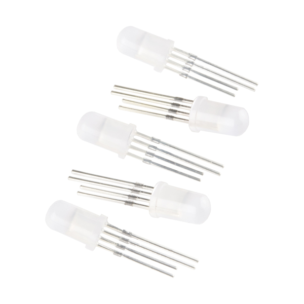
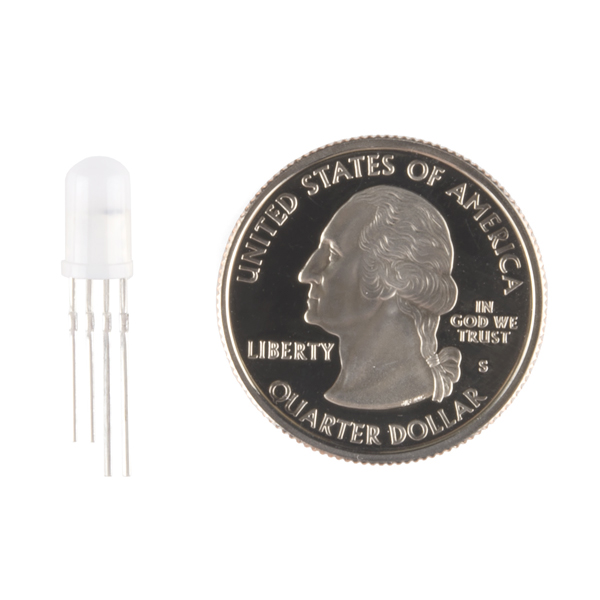
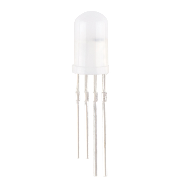
LED - RGB Addressable, PTH, 5mm Diffused (5 Pack)
We know these look like a lot of our other LEDs, but they're not! These are PTH Addressable RGB LEDs with a WS2812 (or "NeoPixel") control IC built right into the them. This PTH version is incredibly similar to its SMD cousin, except it is a lot simpler to solder into your project and is in a diffused 5mm package. This RGB LED has the control IC moved into the actual LED, so we wanted to offer this amazing product to you! They’re great when you need a lot of color from not a lot of board space, now more so than ever.
If you are looking for a great addressable LED in the more common LED form factor, then this is the perfect choice for you.
Note: Comes in packs of 5.
- Power Supply: DC 4.5V - 6V
- Internal Frequency: 800kHz
- Single Wire Single Transmission
LED - RGB Addressable, PTH, 5mm Diffused (5 Pack) Product Help and Resources
WS2812 Breakout Hookup Guide
July 24, 2013
How to create a pixel string with the WS2812 and WS2812B addressable LEDs!
Core Skill: Programming
If a board needs code or communicates somehow, you're going to need to know how to program or interface with it. The programming skill is all about communication and code.
Skill Level: Rookie - You will need a better fundamental understand of what code is, and how it works. You will be using beginner-level software and development tools like Arduino. You will be dealing directly with code, but numerous examples and libraries are available. Sensors or shields will communicate with serial or TTL.
See all skill levels
Core Skill: Electrical Prototyping
If it requires power, you need to know how much, what all the pins do, and how to hook it up. You may need to reference datasheets, schematics, and know the ins and outs of electronics.
Skill Level: Competent - You will be required to reference a datasheet or schematic to know how to use a component. Your knowledge of a datasheet will only require basic features like power requirements, pinouts, or communications type. Also, you may need a power supply that?s greater than 12V or more than 1A worth of current.
See all skill levels
Comments
Looking for answers to technical questions?
We welcome your comments and suggestions below. However, if you are looking for solutions to technical questions please see our Technical Assistance page.
Customer Reviews
4.5 out of 5
Based on 8 ratings:
1 of 1 found this helpful:
They work as described
I wish the pin layout were more usable. A 2 by 2 pinout - on .1" pitch - I would give it 6 stars
1 of 1 found this helpful:
Perfect
Really easy to set up, following adafruit neopixle guide.
1 of 1 found this helpful:
Datasheet doesn't really match parts shipped
The bag is marked "SJ-F5-2811-F" There are two long leads and two short leads, as shown in the photo. However, the data sheet has a different photo and it is unclear which is pin 1 on the shipped parts.
Wired it up assuming flat side was pin 1 but didn't work, don't want to burn out any more without being sure!
3 of 3 found this helpful:
Works great but needs a pinout picture.
These worked as expected but it was hard since the datasheet doesn't match what comes in the bag. Here is a picture of the actual pinout. https://a.pololu-files.com/picture/0J5433.1200.jpg?cdc0daa0c2fd98e38ed59b7d43758c6b
Good, but a big caveat
WARNING: These are not the same RGB LEDs that come in your SIK kit, and are in fact a completely different animal. Entirely my fault/ignorance that I ordered them not knowing this/understanding what they were. That being said, they still get four stars, as I was able to get them working (with a lot more effort than I originally intended and a lot more program space used, but saved on precious pinouts, so a good tradeoff.
I saw/was expecting four pin RGB LEDs like the one in my SIK where you send red/green/blue power on three of the pins, and the fourth is a ground. These LEDs you send DATA on one pin, then you have a power and a ground, which can be common across your whole project (I assume), so you can save a lot of pins (good thing as I needed four of these to match up to four sensors).
I was really nervous when I found out you have to control these with some specific binary via waveform. Luckily I was able to find the Adafruit::NeoPixel library on github that does all that heavy lifting for you. Good thing as that is probably beyond me. Now you have to include this whole library, so if you are using a tiny chip or extremely short on program space, beware.
After maybe an hour reading through the library examples on git and a few snafus with setting them up (they were defaulting to GRB with that library when copying the sample code), I finally got them working and signaling first, second, third, fourth place on our pinewood derby track as I wanted when paired with some QRD 1114 sensors to detect the finishes. So all in all, thumbs up and a good learning experience.
Thank You Sparkfun.
These are great.
I've long been looking for a frosted version that was also PTH. The color uniformity is spot on for the batch of 50 or so I bought. When you make your PCB footprint for these use an elongated pad with the smallest annular ring on the tight axis between pins. I got lots of solder bridges using circular only padstack.
Careful! Part description is not entirely accurate.
Sparkfun describes this APA106 LED as having a WS2812 controller chip built-in. However, while there is a controller chip built-in, it is not a WS2812. It is more like the WS2811 in that the Red and Green control registers are reversed in the serial data stream. Also if you look at the APA106 datasheet you will see that the data timing is not the same as the WS2811/WS2812. The timing for the APA106 LED is 1.76us/bit, where as the timing for the WS2811/WS2812 is 1.25uS/bit. This could cause some control issues if you weren't aware of this and assumed it was equivalent to the WS2812. I'm knocking off one star for the Sparkfun description, not for the parts themselves.
Question
When I purchased some WS2812B 5050 SMD LEDs, I found that I needed to solder in a capacitor across power for each LED. I bought a bunch of these PTH and assumed that I also needed one so I just went straight to it. But do these require a capacitor or is one built into the IC? On another note, I love how easy these are to daisy chain and control! So much easier than trying to control a lot of single LEDs.
While the datasheet makes mention that no external hardware is required, to be safe, I would suggest you use the smoothing capacitor on the power and in line resistor on the data line as shown in this tutorial https://learn.sparkfun.com/tutorials/ws2812-breakout-hookup-guide?_ga=1.248568967.1851504437.1417041706#hardware-hookup


Spark Fun, how about adding a real data sheet. One that has layout dimensions, and pin sizes. There is also and error on the provided data sheet. The current one provided has different pinout numbers. For instance the schematic has pin1 as VDD, yet the photo at the top show pin1 as DIN.
I found it CRUCIAL to add a 330 ohm resistor on the data pin! Without this, if the LED turned red during my program, it stayed red on reset, even though my setup code was initializing it and turning it off. It was very odd and almost random. Only happened when the LED was RED on reset, and seemed intermittent. Very strange, I am still not sure what was going on.
With pot legal in Colorado, it MUST be interfering with updating datasheets and product descriptions!
With the short legs to the left, the pinout for these is 1 - DIN, 2 - VCC, 3 - GND - 4 - DOUT
I was able to power and drive a 5mm Diffused Addressable RGB LED https://www.sparkfun.com/products/12986 using a SparkFun 3.3v Arduino Pro Micro. However, I found that pins 5, 7, and the analog pins DO NOT WORK to drive this (at least with the Adafruit library). See more at http://forums.adafruit.com/viewtopic.php?f=47&t=61188
So since these LEDs have an IC inside them, do I need to add a .1uf capacitor next to each one, or is there already one built in?
I don' think theres a cap inside but it doesn't hurt. FYI put a small resistor(330-550) between the first LED and the data pin or you'll get this weird black cloud in your LED! (somehow it still works!)
Anyone have any information on the brightness of these (mcd)? I didn't see it anywhere in the documentation.
Is it more correct to say these are a "ws2812 package" with a "ws2811 controller IC built in" ? Your description stating ... "with a WS2812 control IC built right" I think is incorrect.
Hi, A WS2811 is the name of the driver on it's own. A WS2812 is the name for a LED with the driver built in. So you are some what correct. However, I do believe this would still fall under a 2812 as it has the LED attached.
Wish I had read the comments about this product. The picture on the data sheet is useless because it does not show lead length. I assumed the longest lead is positive like on most LEDs but it is the GND. So I blew one out of my five-pack.
Adafruit has an excellent pinout photo of this device, see their NeoPixel Clear 5mm Through-Hole LED, product 1837 (a discontinued product). Select the fifth photo from the left for pinout.
Could you please tell me what is the pin spacing and the pin diameter ?
pin spacing is .075" +- .005" (by eye) The legs bend easily enough to fit into a .1" breadboard, but will prevent a flush fit.
I figured out the problem with the DO signal. The Latch signal (50 usec low) is at the end of the data string, not between the 24-bit sequence for each LED. If you leave too much time (> ~5 usec) between 24-bit data, the 1st LED thinks it is at the end of the string and never passes the data through using DO. We need at 'real' datasheet with actual pinouts, timing diagrams, electrical characteristics for the DO line, etc!
I didn't have any trouble getting the 1st LED in a string to work by bit-banging with a PIC, but I'm getting no signal from the DO pin. So, the 1st LED changes colors, but the subsequent LED's in the daisy-change are blue (the start-up color). I tried disconnecting the 1st LED, pulling it up with a 1k resistor, but this just gives a DC voltage to rise from ground to ~2V. Maybe I have a defective batch? I tried switching other LED's into the 1st position with the same result. I'm using the pinout that wawison described.
Make sure you protected the data and the first LED with a resistor(330-550) and check Adafruits Neopixel guide cause these addressable LED's are really picky ( cause that's all they are really)
I ordered a bunch of these. It would be nice to get the pinout and lead diameter as well as the lead spacing so I can start laying out my board.
Anybody?
Yes- that IS a horrible datasheet. Anybody also have any idea on the max current draw?
Anyone have an eagle part for this? Just want to make sure I get the pinout right. Also, the data sheet image looks different than the picture. Which side is pin one?
did you find a eagle part?
How exactly does one program a strip of these to have specific LEDs show specific colors? The datasheet shows the Dout chained to the next Din but how do you make a specific color show for a specific LED?
Any pointers to a usage guide?
A buddy of mine posted an Instructable on it, http://www.instructables.com/id/Demystifying-4-pin-addressable-RGB-LEDS/ includes example code.
That is an excellent instructable. Thank you for sharing.
Yeah, the DS that we have gotten from our supplier is not good at all. We are currently working on updating our WS2812 Hookup Guide by adding a section for these and the 8mm Addressable PTH LEDs. That way you should have all the instruction you need! :)
You can always check adafruit (they have these as 'NeoPixels') as they have a usage guide. But basically each led takes 24 bit color information (RGB) and you send out 24 bits x however many LEDs you have chained and the IC removes its color data and forwards the remaining to the next in line. There are very specific timings needed but its doable with arduinos.
Be good getting this with a clear lens.
Are you looking to project mixed light? The clear-lensed RGB LEDs I've seen so far tend to splay the different colors. Since each color comes from a different die, they can't all be located in the center of the epoxy. So, on the clear RGB LEDs I've seen, one color will project straight, but the other two will be at a slight angle.
Search for COM-12999... they're the clear variety.
Does anyone know if there is a variety of this LED in a 10mm diffused format?
I don't think so, but I would check Adafruit for the full line of NeoPixels.