SparkFun LiPower Shield
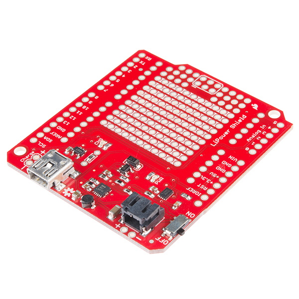
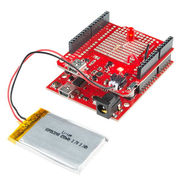
Is there anything an Arduino can't do? Well, for one, most of them can't be powered directly from a 3.7V LiPo battery; much less charge and monitor that battery. The SparkFun LiPower Shield takes care of this by combining the functionality of two of our favorite battery power boards: the Power Cell and the Fuel Gauge.
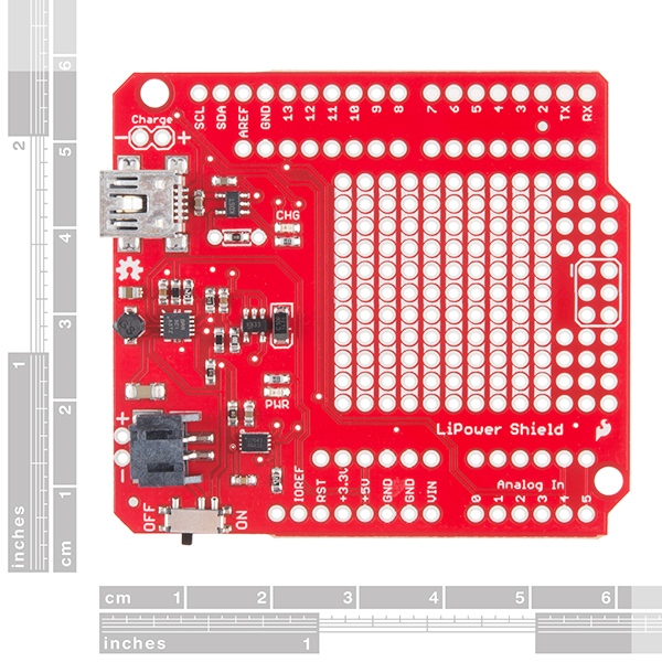
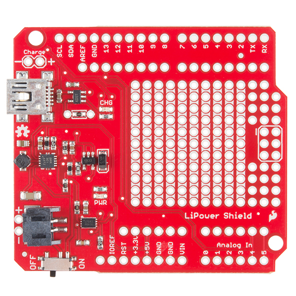
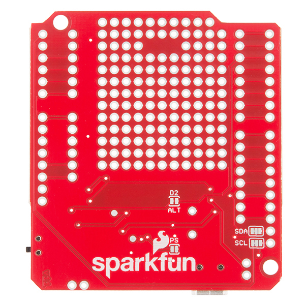
The LiPower Shield allows you to connect a 3.7V single cell Lithium polymer battery which it will boost up to 5V and connect to the Arduino board's 5V pin. The on-board MAX17043G+U IC is connected to the I2C lines (A4 and A5) so that your project can monitor it's own power supply. The configurable alert interrupt pin on the MAX17043G+U IC is broken out to D2 which will activate when the LiPo gets to 32% or lower.
The charging circuit is configured to charge the LiPo at 100mA but by adding a resistor to the supplied through-holes you can boost this to 500mA. There is a mini-USB port on the shield which allows you to charge the battery from a USB power source or you can supply a separate regulated 5V source on the "charge" header.
SparkFun LiPower Shield Product Help and Resources
**Power Warning!**
A word of warning - If you're trying to connect the shield to an Arduino, make sure that the shield is not powered as you connect them. Connecting the device while powered seems to blow out the boost regulator on the board, causing an irreparable failure.
Core Skill: Soldering
This skill defines how difficult the soldering is on a particular product. It might be a couple simple solder joints, or require special reflow tools.
Skill Level: Rookie - The number of pins increases, and you will have to determine polarity of components and some of the components might be a bit trickier or close together. You might need solder wick or flux.
See all skill levels
Core Skill: Electrical Prototyping
If it requires power, you need to know how much, what all the pins do, and how to hook it up. You may need to reference datasheets, schematics, and know the ins and outs of electronics.
Skill Level: Rookie - You may be required to know a bit more about the component, such as orientation, or how to hook it up, in addition to power requirements. You will need to understand polarized components.
See all skill levels
Comments
Looking for answers to technical questions?
We welcome your comments and suggestions below. However, if you are looking for solutions to technical questions please see our Technical Assistance page.
Customer Reviews
4 out of 5
Based on 1 ratings:
1 of 2 found this helpful:
Good, but may be flawed
The functionality and capability of this board is good, and a good buy. At first I had a problem with the board not outputing any power to the rest of the system. That was fixed by Bobby at Sparkfun. Now I have a problem with the battery I got, a 3.7V, 850 mAh LiPo unit. It will not accept a charge. I believe it is damaged, either from charging from the new battery shield, or from the old one. It sits at 3.28V and does not charge to any higher voltage. This is about a battery that was connected to this board. Sparkfun has been very helpful and responsive on issues to this point.

Bought 2 boards, both blew up. First one when connecting to Arduino with switch in ON position, second one made sure to keep it off, but while battery was charging via 5V supply.
Garbage design and implementation, with misleading description (at least the snippet is there).
When the USB for the shield is plugged in -- "chg" LED is on -- and switch is on -- should I see 5V on the +5V arduino pin?
Should I see voltage on the battery jack?
Switch on -- zero volts at battery jack. Switch off battery's 3.86V at battery jack. Something seems to be backwards or missing here.
The battery is at 3.86V when disconnected from shield. When connected, there doesn't seem to be any output voltage, with battery or with charging wire connected.
It seemed to have worked nicely for several days. Reporting 60% battery level. Today I (finally) plugged in a USB to the charger port -- charging light came on.
Now, there seems to be no output voltage. When plugged in to USB power the PWR led seemed to flash briefly when the switch was set to on.
It seems unlikely the battery is dead at 3.86V. I see warnings in the support tips "make sure that the shield is not powered as you connect them" Does this mean no battery when you connect them? Or does it mean no USB power when you connect them?
If I connect the Arduino serial while ALSO connecting the LiPower charging USB, was this the fatal mistake that fried something?
can this board operate from a battery while the arduino is plugged in? I would like to use the serial monitor while using the lipower shield.
Is this fellow wearing the same chip as the LiPo Fuel Gauge TOL#10617?
Does this revision 'cure' the cell-killing low-voltage bug of the previous versions?
Anyone else having trouble with the charging amperage calculation for the MCP73831T? The data sheet and the SparkFun schematic both say it's calculated as: I = 1000V / R where: I = charging current in milliampere R = programming resistor in kOhms
What is V? Without V the formula works: 100u = 1000 / 10kOhm
According to the data sheet V appears to be Input voltage. Unfortunately, when including V in the formula, everything breaks: 100u =/= 1000 x 5v / 10kOhm
Anyone know what I'm missing?
Yeah, lots of confusing units in that equation. 'V' is just the units of that 1000 value -- voltage. And remember R is the program resistor's value in kiloohms (kΩ), and the result of the equation is the charge current in miliamps (mA). So a 10kΩ resistor sets the charge current to 1000 / 10 or 100mA.
If you add an external resistor to the board, it'll be in parallel with the 10kΩ already on there. An example provided in the schematic shows that a 2.5kΩ added to the board will set the charge current to about 500mA: 1000 / (10k || 2.5k) = 1000 / 2k = 500mA.
Oh my God! Thank you for explaining it so nicely! I was going crazy trying to figure out what the V represented. =D
I was trying to figure out how build something like this and SparkFun to the rescue. And, of course, it's backordered. LOL!
Mini-USB? What kind of monster are you? Hasn't the world moved almost 100% to micro-USB for charging?
They pretty much have, which is why everyone is using all of their micro-USB cables, but has all their Mini-USB cables laying around unused! Honestly I don't think we thought about changing it on the revision and our Mini-USB connectors are a lot more secure.
I'm in the same boat! Don't want to have a bunch of cables lying around. How hard is it to change the connector? - or - will the board take a charge current from the Arduino VIN
A MicroB USB connector is not going to have the same footprint, so you will probably have a tough time swapping the connector out. Looking at the schematic it does not look like you can charge the board from the Vin pin which is probably because the charger needs 5V and the Arduino board should have more than 5V on the Vin line. We are getting more and more microB products, but MiniB will still be around for a bit.
The above description says the "alert interrupt pin on the MAX17043G+U IC is broken out to D3" pin; however the schematic says it goes to the D2 pin.
Updated, thank you!