Load Cell - 10kg, Straight Bar (TAL220)
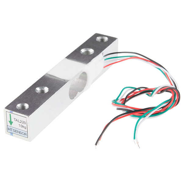
This straight bar load cell (sometimes called a strain gauge) can translate up to 10kg of pressure (force) into an electrical signal. Each load cell is able to measure the electrical resistance that changes in response to, and proportional of, the strain (e.g. pressure or force) applied to the bar. With this gauge you will be able to tell just how heavy an object is, if an object's weight changes over time, or if you simply need to sense the presence of an object by measuring strain or load applied to a surface.
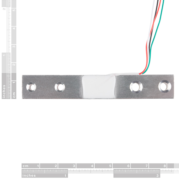
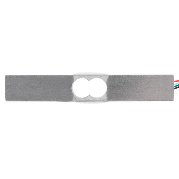
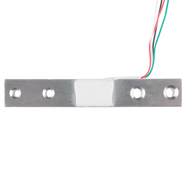
Each straight bar load cell is made from an aluminum-alloy and is capable of reading a capacity of 10kg. These load cells have four strain gauges that are hooked up in a wheatstone bridge formation. The color code on the wiring is as follows: red = E+, green = O+, black = E-, and white = O-. Additionally, these load cells offer an IP66 protection rating and feature two M4 and two M5 sized through-holes for mounting purposes.
- 80mm x 12.7mm x 12.7mm, 250mm Wire
Load Cell - 10kg, Straight Bar (TAL220) Product Help and Resources
OpenScale Applications and Hookup Guide
July 22, 2016
OpenScale allows you to have a permanent scale for industrial and biological applications. Learn how to use the OpenScale board to read and configure load cells.
Getting Started with Load Cells
June 11, 2015
A tutorial defining what a load cell is and how to use one.
Load Cell Amplifier HX711 Breakout Hookup Guide
July 22, 2016
A hookup guide for the HX711 load cell amplifier breakout board
Qwiic Scale Hookup Guide
April 11, 2019
Create your own digital scale quickly and easily using the Qwiic Scale!
Core Skill: Soldering
This skill defines how difficult the soldering is on a particular product. It might be a couple simple solder joints, or require special reflow tools.
Skill Level: Noob - Some basic soldering is required, but it is limited to a just a few pins, basic through-hole soldering, and couple (if any) polarized components. A basic soldering iron is all you should need.
See all skill levels
Core Skill: Electrical Prototyping
If it requires power, you need to know how much, what all the pins do, and how to hook it up. You may need to reference datasheets, schematics, and know the ins and outs of electronics.
Skill Level: Rookie - You may be required to know a bit more about the component, such as orientation, or how to hook it up, in addition to power requirements. You will need to understand polarized components.
See all skill levels
Comments
Looking for answers to technical questions?
We welcome your comments and suggestions below. However, if you are looking for solutions to technical questions please see our Technical Assistance page.
Customer Reviews
4 out of 5
Based on 3 ratings:
1 of 1 found this helpful:
Worked but hard to use
I'm a beginner so it was a little challenging to get going, but for the most part I found resources on this website and it it working.
1 of 1 found this helpful:
I'm torn. I love it! But I hate the tiny wires
Works how it is supposed to, but the absurdly tiny gauge of these wires is an absolute nightmare. Maybe my problem is that I don't want to solder these things into the hx711 quite yet.
I just wanted to make sure it works and get everything set up and calibrated, but I have no idea how to get a consistent connection between these wires and the holes on the hx711 (which is crucial to getting an accurate and consistent reading).
Maybe I can find something to clamp them into? Sparkfun, please save me! I love you and I know its not your fault! Its a tiny $7 load cell from china. I just want to get a solid connection for bread board if possible.
Thank you, if you read this sparkfun people.
Okay just realized you do say it requires a little bit of soldering. So I changed it back to five stars. I will give it a go. First real world project attempt.


Whats the minimum detectable weight, and whats the increments?
I see that this part has M4 and M5 holes, but its not clear the thread pitch. I can easily find M4 bolts in four different thread pitches and M5's in three different tread pitches.
How do I have to apply the load? Does the measurement change when applying the same load to the inner or outer hole?
Can one of these paired with something like a joule thief generate any usable current if integrated into a kayak paddle?
Unfortunately no. A load cell is really just 4 fancy resistors connected in a Wheatstone bridge. They don't generate any electric current at all.
Can the 10kg range be extended by placing a counter weight in the opposite direction? Is the sensitivity valid and/or consistent in both loading directions?
@774106 - With this type of load cell, you could construct a brake dynamometer (https://en.wikipedia.org/wiki/Dynamometer). You would need something for the shaft to turn against, for example a water brake, eddy current discs, electric motor, etc. That brake would be mounted on a bearing, allowing it to turn. A bar or post mounted radially to the brake is used to scale the amount of force you want (longer = less force measured at the end). That is where you attach a load cell like this, the other end of the load cell would be mounted rigidly.
If you want a true torque sensor, which measures the deflection of a rotating shaft, and then provides that voltage to instrumentation via a slip ring, be prepared for much more expensive components.
please can this be used to measure the torque of a rotating shaft
Similarly, the load cells I received have two tapped M4 holes on one end, and two tapped M5 holes on the other. All other dimensions are accurate.
Note, the one I received has two tapped M6 holes and two M8 (? M6 screws pass cleanly through, anyway) tapped holes like the picture shows and unlike the description.