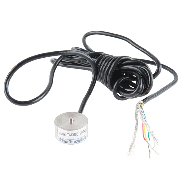
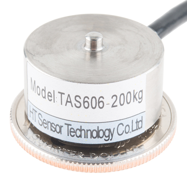
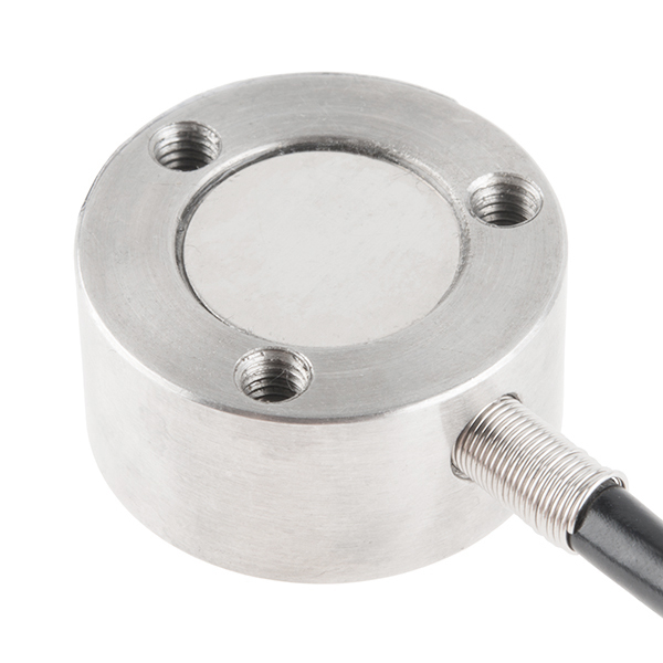
This disc load cell (sometimes called a strain gauge) can translate up to a whopping 200kg of pressure (force) into an electrical signal. Each load cell is able to measure the electrical resistance that changes in response to, and proportional of, the strain (e.g. pressure or force) applied to the disc. With this gauge you will be able to tell just how heavy an object is, if an object's weight changes over time, or if you simply need to sense the presence of an object by measuring strain or load applied to a surface.
Disc load cells are a bit easier to mount than bar-style load cells, making them more straightforward to implement into a design.
Each load cell is made from an steel-alloy and is capable of reading a capacity of 200kg. These load cells have four strain gauges that are hooked up in a wheatstone bridge formation. The color code on the wiring is as follows: red = E+, green = O+, black = E-, and white = O-. Additionally, these load cells offer an IP66 protection rating.
- 20mm x 11mm, 2000mm Wire
Load Cell - 200kg, Disc (TAS606) Product Help and Resources
OpenScale Applications and Hookup Guide
July 22, 2016
OpenScale allows you to have a permanent scale for industrial and biological applications. Learn how to use the OpenScale board to read and configure load cells.
Getting Started with Load Cells
June 11, 2015
A tutorial defining what a load cell is and how to use one.
IoT Industrial Scale
October 10, 2016
What does a baby elephant weigh? How much impact force does a jump have? Answer these questions and more by building your very own IoT industrial scale using the SparkFun OpenScale.
Load Cell Amplifier HX711 Breakout Hookup Guide
July 22, 2016
A hookup guide for the HX711 load cell amplifier breakout board
Qwiic Scale Hookup Guide
April 11, 2019
Create your own digital scale quickly and easily using the Qwiic Scale!
Core Skill: Soldering
This skill defines how difficult the soldering is on a particular product. It might be a couple simple solder joints, or require special reflow tools.
Skill Level: Noob - Some basic soldering is required, but it is limited to a just a few pins, basic through-hole soldering, and couple (if any) polarized components. A basic soldering iron is all you should need.
See all skill levels
Core Skill: Electrical Prototyping
If it requires power, you need to know how much, what all the pins do, and how to hook it up. You may need to reference datasheets, schematics, and know the ins and outs of electronics.
Skill Level: Rookie - You may be required to know a bit more about the component, such as orientation, or how to hook it up, in addition to power requirements. You will need to understand polarized components.
See all skill levels
Comments
Looking for answers to technical questions?
We welcome your comments and suggestions below. However, if you are looking for solutions to technical questions please see our Technical Assistance page.
Customer Reviews
4.5 out of 5
Based on 4 ratings:
Things are working good.
Good
I'm still figuring out how to program the whole thing,
Good Product
It works very well Lawrence Windrem President Gaming Essentials Inc.


Is there going to be a 100kg load cell coming at all to fill the gap between 50kg and 200kg?
I see these are IP66 rated... Can anyone comment on how that translates to use outdoors. It would be exposed to rain and condensation over time. Any concerns with the moisture exposure in those conditions?
Accodring to IP66: IP66 Enclosure - IP rated as "dust tight" and protected against heavy seas or powerful jets of water.
If one had access to a machine shop (i.e. mill, lathe), could this be modified to read tension? I.e. have you ever opened one of these up and looked at the insides? It looks like the 'top' is probably a really thin web, and perhaps it would be drilled and tapped if they left enough meat on it.
Any ideas of how I can build a platform for this type of load cell? Thanks.
Specs show mounting with M2 with 4 holes. Actual is M? with 3 holes. Conclusion: Wait for delivery before drilling holes.
I found M3 fits. I found the following wiring: E+ Red E- Green A- Yellow A+ White
I just received this load cell and noticed your other comment about the leads being the wrong colors - can you share what the correct color mapping is for the 200kg cell?
Edit - nevermind, busted out the ohmmeter. red and green are excitation, yellow and white are output.
I just got this too and can't get it working and so I'm wondering if the wiring is still indicated wrong. How exactly do you tell which are excitation and which are output?
I used an ohmmeter and both red-green and red-black have resistances.
Thank you
What is the total weight of this load cell which can translate up to 200kg axial load?
I followed the instructions of the hookup guide and used red and green as excitation and yellow and white as output. But the example sketch is still reading 0 lbs regardless of weight, too. Does someone know the solution for this?
How can you determine the force output from the voltage?
hooked this load cell up per the instructions on the load cell hookup guide, but the example sketches are reading 0 lbs regardless of weight. Assumed the yellow wire is E- (since there is no black).
Edit - nevermind, busted out the ohmmeter. red and green are excitation, yellow and white are output.
I just got this too and can't get it working and so I'm wondering if the wiring is still indicated wrong. How exactly do you tell which are excitation and which are output?
I used an ohmmeter and both red-green and red-black have resistances.
Thank you