SparkFun Load Sensor Combinator
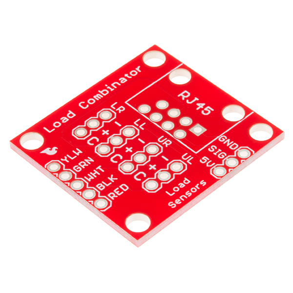
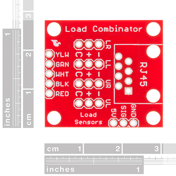
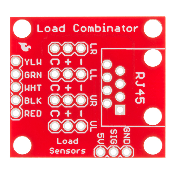
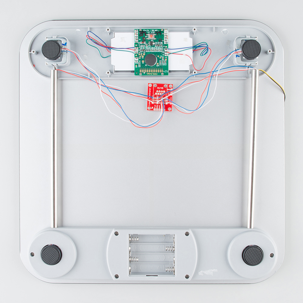
The SparkFun Load Sensor Combinator is a bare PCB that combines four load sensors into a standard four-wire Wheatstone bridge configuration. If you open up an electronic bathroom scale, you’ll find a large rat's nest of wires. The Load Sensor Combinator was created to combine the 12 wires found in a bathroom scale into the standard four-wire Wheatstone bridge configuration.
This version of the SparkFun Load Sensor Combinator features a few changes that you specifically asked for! We updated the silk on the breakout to read "C/+/-" instead of "R/W/B" and moved the temperature sensor connector away from the standoff hole.
You can either use four individual load sensors or simply purchase an off-the-shelf bathroom scale and hack the combinator into it rather than trying to design a base to properly mount four load sensors.
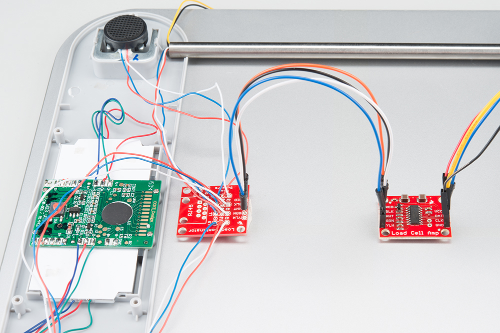
This board works great with our Load Cell Amplifier breakout board; the five pins on the edge of the combinator line up directly to the five pins on the amplifier.
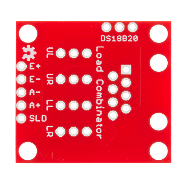
If your amplifier and supporting electronics are more than a few inches away from the scale, an RJ45 footprint is provided. The four Wheatstone pins (E+/E-/S+/S-) as well as the shield pin are connected to twisted pairs within a standard cheap Ethernet cable. This allows the amplifier board to be placed many feet away from the scale itself.
The combinator board also includes a footprint for the DS18B20 one-wire temperature sensor. This allows the user to gather the temperature of the scale in case there is a large variance between the scale and the amplifier. These three pins are accessed through the RJ45 connection as well, allowing remote temperature readings to be gathered over one twisted pair Ethernet cable.
NOTE: The SparkFun Load Sensor Combinator will only work with 3 wire load sensors, it is not compatible with 4 wire load cells.
SparkFun Load Sensor Combinator Product Help and Resources
Getting Started with Load Cells
June 11, 2015
A tutorial defining what a load cell is and how to use one.
Where is the HX711 library?
You may have noticed that the HX711 library isn't in our Github repository. It can be found and downloaded here: https://github.com/bogde/HX711
Core Skill: Soldering
This skill defines how difficult the soldering is on a particular product. It might be a couple simple solder joints, or require special reflow tools.
Skill Level: Rookie - The number of pins increases, and you will have to determine polarity of components and some of the components might be a bit trickier or close together. You might need solder wick or flux.
See all skill levels
Comments
Looking for answers to technical questions?
We welcome your comments and suggestions below. However, if you are looking for solutions to technical questions please see our Technical Assistance page.
Customer Reviews
5 out of 5
Based on 3 ratings:
1 of 1 found this helpful:
Good quality
Easy to use!
Does just what it's supposed to.
However, I bought this and later realized you don't actually need this board. A RJ-45 breakout was all I should have purchased. Never the less this is 100% what it claims to be.
Great Board
Makes My World easy

can you hook up just 2 load cells to combinator?
how do you connect four 4-wire load cells such as the tal220 to this combinator?
Hi, I bought load cells TAS606. Is it possible to connect them with this combinator and using only one amplifier? Or is this only for load sensor? Is there any other chance to connect more than one cell to an amplifier? Or should I buy 4 amplifiers, but then using 2x4 pins on my board? Thank you
You don't need this board, simply connect the TAS606 directly to one amplifier.
The version I got (v 10) have been printed R/B/W; I strongly suggest to keep it C/+/- as in the version in the picture as it would make it easier to use the actual wire instead of being confused by the colors.
Yep, we had enough comments/problems with the labeling on the v10 that we updated the labeling in the new version. This is actually the main difference between the two version.
I have connected 4 "SEN-10245" load cells with cables of around 1 meter to reach a greenhouse. Im getting changes of +/- 1 kg during constant load measurment over 24 h. Is it bacause the load cells are not made for constant load or maybe because i have too long cables(as stated in the description: "If your amplifier and supporting electronics are more than a few inches away from the scale, an RJ45 footprint is provided")
Thank you for an answer!
Hi there, it sounds like you are looking for technical assistance. Please use the link in the banner above, to get started with posting a topic in our forums. Our technical support team will do their best to assist you.
That being said, based on the specifications in the datasheet for the load cell, I believe that might be a limitation of the load cell's accuracy. Here are some links on that topic:
I want to ask can we only hook 2 load cells and carry out the operations further?
What should I do if I only have use of 2 load cells?
HEY! I'm really quite worried after buying four 200 kg load cells, 1 load combinator and 1 load cell amplifier that I may have screwed up. My load cells have 4 wires and the load combinator has only 3 inputs for the "load sensors" that a "Typical bathroom scale" uses. I understand this has something to do with the wheatstone bridge by I don't know which 3 wires to use and what to do with the last one! Please help!
Is it possible to use this combinator if the load cells are not equidistant in a square? (and you want to have the same weight on multiple locations on the scale). For example when load cells are placed in a rectangle or an isosceles triangle?
can this combinator combine for load cells (cells with 5 cables like tas606)??
I'm wondering how long a Cat6 cable I can run between the combinator and the amplifier before the wire resistance starts to become a factor?
I've tried multiple ways of wiring this together with the HX711 and only ever get 0 or nonsensical values (the same as being unplugged). A 0 suggests the bridge is balanced, so what have I wired wrong? Red - S, Black - -, White - + and I even tried reversing a single cell polarity but nothing works.
Do you share schematics? I'm interested in understanding how the wheatstone configuration was implemented in this board.
Yes we do. If you look under the documents section the schematic for the board is available as a PDF. We also have the board files available that you can view in Eagle if you'd like to take a look.