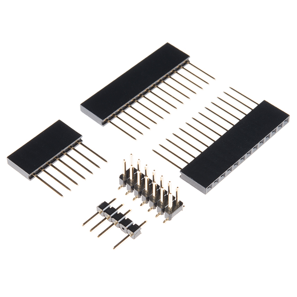
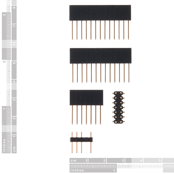
These headers are made to work with the Teensy 4.0, Teensy 3.2, and Teensy LC development boards. Each kit of headers makes your Teensy breadboard compatible and will allow for stacking a Teensy and Teensy-compatible shield board. This kit includes five headers (two 13-pin, one 7-pin, one 3-pin, and one 2x7 right-angle SMT), enough to connect your chosen Teensy in any configuration you need!
Note: This Header Kit can also be used for the Teensy 3.0 and 3.1, as the pin layout has not changed between the three versions.
- 2x 13-pin stackable header
- 1x 7-pin female header (for pins on end)
- 1x 3-pin header (for 3-off grid holes)
- 1x 2x7 right-angle SMT header, for the surface mount pads on the back of the Teensy 3.2
Teensy Header Kit Product Help and Resources
Getting Started with the Teensy
June 18, 2015
Basic intro to the Teensy line of products, with soldering and programming suggestions.
Core Skill: Soldering
This skill defines how difficult the soldering is on a particular product. It might be a couple simple solder joints, or require special reflow tools.
Skill Level: Rookie - The number of pins increases, and you will have to determine polarity of components and some of the components might be a bit trickier or close together. You might need solder wick or flux.
See all skill levels
Comments
Looking for answers to technical questions?
We welcome your comments and suggestions below. However, if you are looking for solutions to technical questions please see our Technical Assistance page.
Customer Reviews
No reviews yet.


As others have said, these are NOT suitable for Teensy 4.0. 4.0 requires 14 pin headers, these are 13
This product is technically compatible with the Teensy 4.0 as the 7-pin header fills in the last, 14th-pin on the development board. However, I have noted the other customer comments and will pass the information to our catalog team (that a 14-pin (x2) and 5-pin (x1) configuration is preferred).
Update: Due to the extra length required for the ends of the header, a (2x) 14-pin with a (1x) 5-pin header will have more tolerance issues (aka they don't fit nicely together). Squeezing a 5-pin header in between two 14-pin headers will force the 14-pin headers outwards (i.e. sort of like this \~~~/, when looking down the side of the USB connector).
Even though it's linked from the Teensy 4.0 page as an essential, this header is 13pins not 14pins like the Teensy 4.0
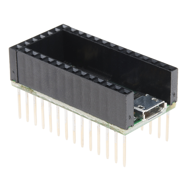
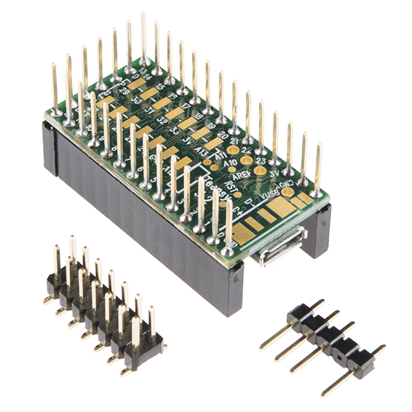
That is correct, there are two 13 pin headers and the 7 pin header attaches to the end of the board for that "last" pin (shown in last 2 product images).
It should be two 14-pin headers and one 5-pin to go across the bottom if required.
Why did you change this from two 14-pin headers and one 5-pin header to two 13-pin headers and one 7-pin header? Now it doesn't work with the audio board!
Hides the button so you cant press it for programming and doesn't work with audio shield, contains 13 pin header but it should be 14 ... it is a big mystery for me why sparkfun offers 13 pin headers ... : /