Arduino MKR1000 (with Headers)
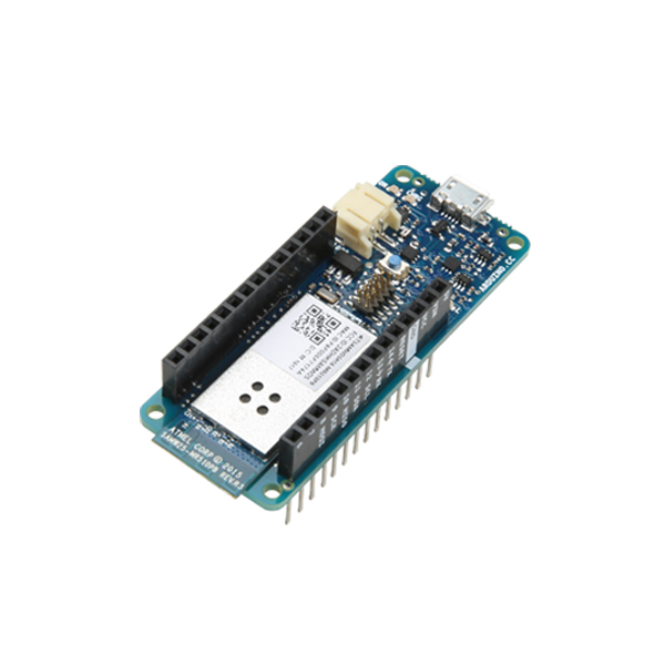
The Arduino MKR1000 is a powerful board that combines the functionality of an Arduino Zero and a handy WiFi shield. This thin board has been designed to offer a practical and cost-effective solution for makers wanting to design IoT projects with minimal previous experience in networking. It is based on the Atmel® ATSAMW25 SoC (System on Chip), which is part of the SmartConnect family of Atmel wireless devices specifically designed for Internet of Things (IoT).
The MKR1000 design includes a LiPo charging circuit that allows the Arduino to run on battery power or external 5V, charging the LiPo battery while running on external power. Switching from one source to the other is done automatically. A good 32-bit computational power similar to the Arduino Zero board, the usual rich set of I/O interfaces, low-power WiFi with a Cryptochip for secure communication, and the ease of use of the Arduino Integrated Development Environment (IDE) for code development and programming. All of these features make this board the preferred choice for the emerging IoT battery-powered projects in a compact form factor. The USB port can be used to supply power (5V) to the board. The Arduino MKR1000 is able to run with or without the LiPo battery connected and has limited power consumption.
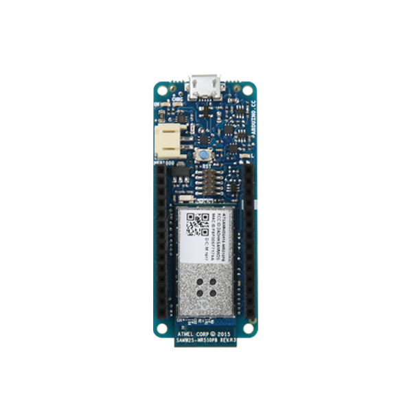
Note: This version of the Arduino MKR1000 has labeled, stackable headers already mounted to the board. If you would like an MKR1000 without headers pre-mounted, purchase this version instead.
- Microcontroller: SAMD21 Cortex-M0+ 32-bit low-power ARM MCU
- Board Power Supply (USB/VIN): 5V
- Circuit Operating Voltage: 3.3V
- Digital I/O Pins: 8
- PWM Pins: 12
- Flash Memory: 256 KB
- SRAM: 32 KB
- Full-speed USB device and embedded host
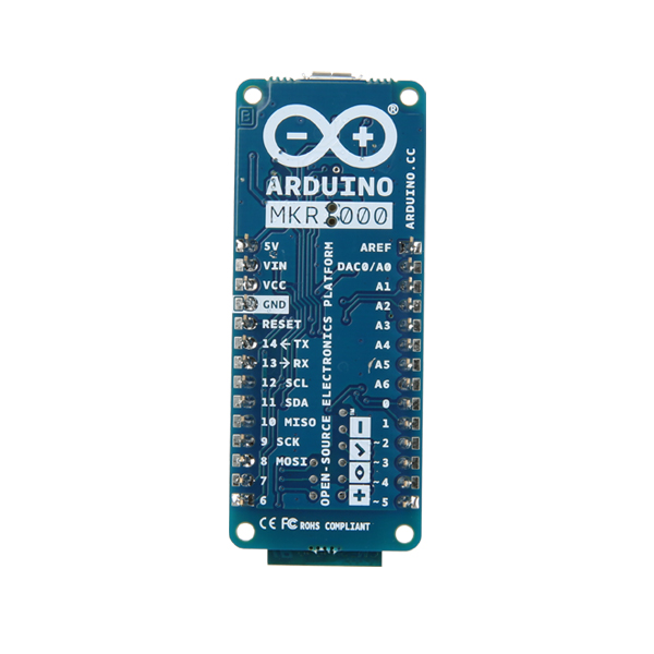
- Pre-mounted headers with pin-out
- Arduino Part #: ABX00011
Arduino MKR1000 (with Headers) Product Help and Resources
Adding More SERCOM Ports for SAMD Boards
February 4, 2019
How to setup extra SPI, UART, and I2C serial ports on a SAMD-based boards.
Conductive Foam Backing
The anti-static foam backing used to protect the headers is slightly conductive and may cause issues if the MRK1000 is still sitting in it. Removing the board from the backing should resolve any power or device connectivity issues to the board you were seeing earlier.
Core Skill: Programming
If a board needs code or communicates somehow, you're going to need to know how to program or interface with it. The programming skill is all about communication and code.
Skill Level: Rookie - You will need a better fundamental understand of what code is, and how it works. You will be using beginner-level software and development tools like Arduino. You will be dealing directly with code, but numerous examples and libraries are available. Sensors or shields will communicate with serial or TTL.
See all skill levels
Core Skill: Electrical Prototyping
If it requires power, you need to know how much, what all the pins do, and how to hook it up. You may need to reference datasheets, schematics, and know the ins and outs of electronics.
Skill Level: Rookie - You may be required to know a bit more about the component, such as orientation, or how to hook it up, in addition to power requirements. You will need to understand polarized components.
See all skill levels
Comments
Looking for answers to technical questions?
We welcome your comments and suggestions below. However, if you are looking for solutions to technical questions please see our Technical Assistance page.
Customer Reviews
4 out of 5
Based on 1 ratings:


Question: I note: "includes a LiPo charging circuit that allows the Arduino to run on battery power or external 5V, charging the LiPo battery while running on external power. Switching from one source to the other is done automatically." Excellent.
AND the board has a "Vin" input... an alternate power input option> ...which could be given.. what range of voltages, please? And if the device were powered that way, would the LiPo charging proceed as if the device powered from USB line?
What's on my mind is this: Could the Vin be powered by (appropriate!) solar panels, using the "self-charging" battery to tide the whole system over the night? Would the source of voltage from the solar panels need some sort of "turn it off" circuit, for when the voltage from the solar panels was too low? Would the voltages concerned fall into ranges that allowed that "circuit" to be a simple diode, if the designer were willing to sacrifice maximum charging for minimun hassle? // Thanks!
Looking at the schematic, the Vin input goes to a AP7215-33YG-13 voltage regulator through a shottky diode. The regulator has a maximum input of 5.5V, and the shottky diode will have a drop of around 0.2V. So max input is 5.7V absolute maximum.
To use a solar cell, add a buck/boost switching regulator with an output of 5V between it and the MKR1000 Vin pin.
Note: The minimum input voltage for the regulator is 3.4V to 3.55V depending on load current, so you will not get full use of a LiPo battery which has a range of 3.0V to 4.2V. You need to look at the characteristics of the cell you use to check how much capacity is available above 3.5V.
Hope that helps. Please correct me if I misinterpreted anything!
Andy
Very helpful! The idea that Vin on some Arduinos cannot be given voltages above 5.7 (and that's the LIMIT, something lower as "the plan" would be better) was new to me... but then, I started when they were all 5v. So... even if my solar cell idea goes nowhere, I've learned something important.
Any thoughts on the second part of my question? Will there be any harm in leaving the solar panels (though converter) connected, even when it gets dark, and they aren't producing a voltage? Would some "turn it off" ("disconnect") circuit be needed? ("Not sure" is a perfectly acceptable answer, if that's the case... please only say "no" if sure!) (Hints as to what that circuit might be would be welcome, if the answer is, alas, "yes")