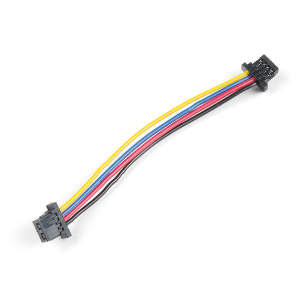
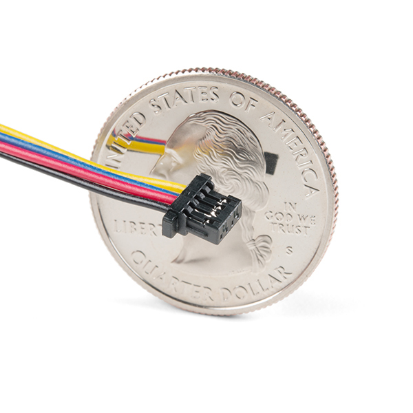
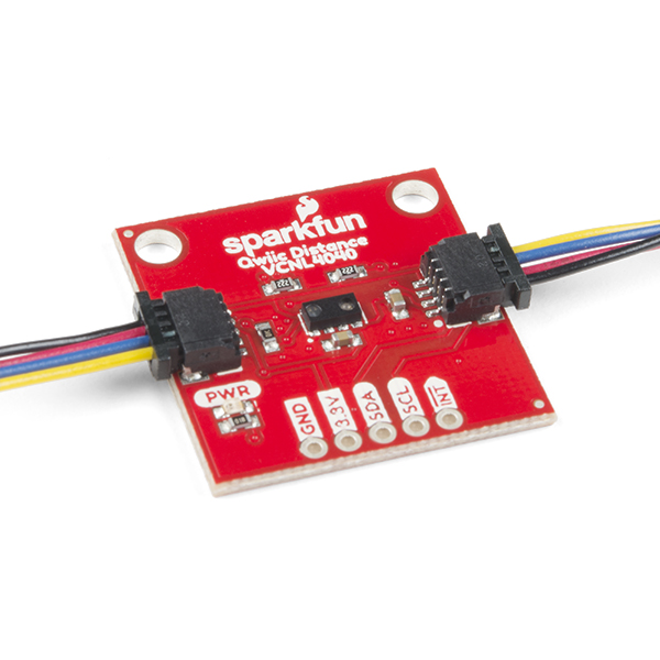
This is a 50mm long 4-conductor cable with 1mm JST termination. It’s designed to connect Qwiic enabled components together but can be used for other applications as well.
Each Qwiic Cable's wires have been color coded to red, black, blue and yellow.
The SparkFun Qwiic connect system is an ecosystem of I2C sensors, actuators, shields and cables that make prototyping faster and less prone to error. All Qwiic-enabled boards use a common 1mm pitch, 4-pin JST connector. This reduces the amount of required PCB space, and polarized connections mean you can’t hook it up wrong.
- Dimensions: 50mm (1.96") Length
Qwiic Cable - 50mm Product Help and Resources
GPS Geo-Mapping at the Push of a Button
September 27, 2019
Let's ramp up our GPS tracking skills with KML files and Google Earth. We'll make a tracker that logs location and allows us to visualize our steps with Google Earth.
Power Delivery Board - USB-C (Qwiic) Hookup Guide
February 13, 2020
This guide will go over how to use the USB Type-C Power Delivery Board.
Qwiic Digital Indoor Thermometer
July 15, 2020
Qwiic-ly build a digital indoor thermometer to measure the ambient temperature of the room and display it using an OLED on an I2C bus!
SparkFun Qwiic Alphanumeric Display Hookup Guide
October 21, 2021
A Hookup Guide to get you started with the Qwiic Alphanumeric Display.
Qwiic GPS Clock
September 14, 2020
What time is it? Time for you to... Qwiic-ly build a GPS clock and output it to a display! This project provides you with the current date and time using GPS satellites. Read the date and time as a digital or analog clock. Or even configure the clock for military, your time zone, or automatically adjust the time for daylight savings time!
Qwiic 9DoF - ISM330DHCX, MMC5983MA Hookup Guide
July 28, 2022
Find all your degrees of freedom with this little Qwiic breakout board combining the ISM330DHCX 6Dof and the MMC5983MA Magnetometer!
SparkFun Temperature Sensor - STTS22H (Qwiic) Hookup Guide
January 19, 2023
Get started with the ultralow-power, high-accuracy, qwiic-enabled SparkFun Temperature Sensor - STTS22H!
Comments
Looking for answers to technical questions?
We welcome your comments and suggestions below. However, if you are looking for solutions to technical questions please see our Technical Assistance page.
Customer Reviews
No reviews yet.


The JST connectors on each end of the cable are rotated 180 degrees (about the long axis of the cable) with respect to each other. So when you connect two QWIIC devices, you have to twist the cable 180 degrees if you want both devices to sit on a flat surface with the component side of each device facing up. Does anyone know why Sparkfun designed the QWIIC cables this way?
By putting a twist in the cable, that enables all Qwiic sockets to be universal. Without the twist, you'd need Qwiic IN and Qwiic OUT connector on each board and would need to pay attention to where you were plugging in devices. Plugging an out into another out (or in to another in) and things would break.
Does anyone know how this differs from the original version?
They do not differ from the original at all, they are just an official SparkFun product now as opposed to an experimental SparkX product.