SparkFun Qwiic Keypad - 12 Button
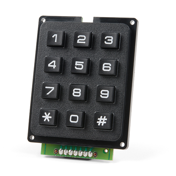
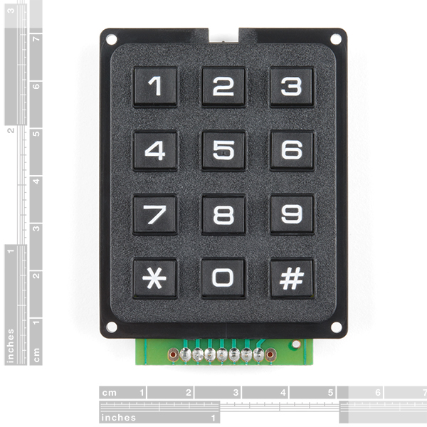
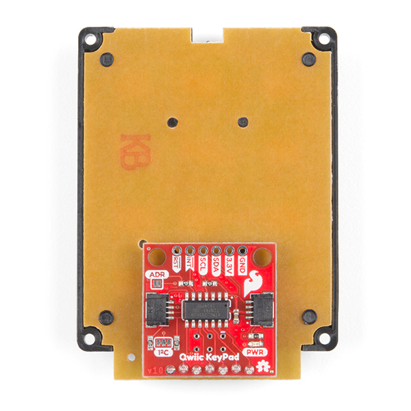
Keypads are very handy input devices, but who wants to tie up seven GPIO pins, wire up a handful of pull-up resistors, and write firmware that wastes valuable processing time scanning the keys for inputs? The SparkFun Qwiic Keypad comes fully assembled and makes the development process for adding a 12 button keypad easy. No voltage translation or figuring out which I2C pin is SDA or SCL, just plug and go! Utilizing our handy Qwiic system, no soldering is required to connect it to the rest of your system. However, we still have broken out 0.1"-spaced pins in case you prefer to use a breadboard.
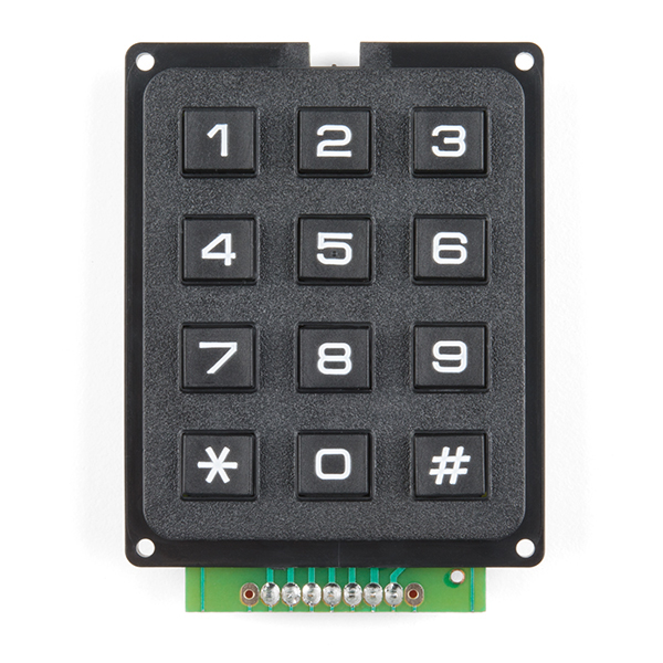
Each of the keypad's 12 buttons has been labeled 1, 2, 3, 4, 5, 6, 7, 8, 9, 0, *, and # and has been formatted to into the same layout as a telephone keypad with each keypress resistance ranging between 10 and 150 Ohms. The Qwiic Keypad reads and stores the last 15 button presses in a First-In, First-Out (FIFO) stack, so you don’t need to constantly poll the keypad from your microcontroller. This information, then, is accessible through the Qwiic interface. The SparkFun Qwiic Keypad even has a software configurable I2C address so you can have multiple I2C devices on the same bus.
NOTE: The I2C address of the Qwiic Keypad is 0x4B and is jumper selectable to 0x4A (software-configurable to any address). A multiplexer/Mux is required to communicate to multiple Qwiic Keypad sensors on a single bus. If you need to use more than one Qwiic Keypad sensor consider using the Qwiic Mux Breakout.
The SparkFun Qwiic connect system is an ecosystem of I2C sensors, actuators, shields and cables that make prototyping faster and less prone to error. All Qwiic-enabled boards use a common 1mm pitch, 4-pin JST connector. This reduces the amount of required PCB space, and polarized connections mean you can’t hook it up wrong.
- Software Selectable Slave Address
- Low Power ATtiny85 controller
- Button Presses w/ Time Stamp
- Default I2C Address: 0x4B
- 2x Qwiic Connector
SparkFun Qwiic Keypad - 12 Button Product Help and Resources
Qwiic Keypad Hookup Guide
April 25, 2019
If you are tired of taking up GPIO pins, wiring a bunch of pull up resistors, and using firmware that scans the keys taking up valuable processing time... check out the new Qwiic Keypad.
Keyboard Shortcut, Qwiic Keypad
April 25, 2019
A simple project using the Qwiic Keypad and the RedBoard Turbo to create your own custom hotkey-pad.
Qwiic Pro Micro USB-C (ATmega32U4) Hookup Guide
February 6, 2020
An overview of the ATmega32U4-based Qwiic Pro Micro USB-C, how to install it, and how to use it with Arduino.
Core Skill: Programming
If a board needs code or communicates somehow, you're going to need to know how to program or interface with it. The programming skill is all about communication and code.
Skill Level: Rookie - You will need a better fundamental understand of what code is, and how it works. You will be using beginner-level software and development tools like Arduino. You will be dealing directly with code, but numerous examples and libraries are available. Sensors or shields will communicate with serial or TTL.
See all skill levels
Core Skill: Electrical Prototyping
If it requires power, you need to know how much, what all the pins do, and how to hook it up. You may need to reference datasheets, schematics, and know the ins and outs of electronics.
Skill Level: Rookie - You may be required to know a bit more about the component, such as orientation, or how to hook it up, in addition to power requirements. You will need to understand polarized components.
See all skill levels
Comments
Looking for answers to technical questions?
We welcome your comments and suggestions below. However, if you are looking for solutions to technical questions please see our Technical Assistance page.
Customer Reviews
3.6 out of 5
Based on 11 ratings:
1 of 1 found this helpful:
When it works it works
This is my third time ordering this device as the first onee came defective and the second keypad stopped working in less than a year. In both cases, certain keys became unresponsive which completely stops one from utilizing the keypad. Hopefully, this one will work longer than a few months.
Qwiic makes use incredibly easy
It probably took three minutes to go from opening the package to having keypad input in my project. I just wish there was a Qwiic version of the 16x2 LCD!
Great Keypad
Example code makes it easy to get up and going quick!! Qwiic connection is convenient
Very Good
I'm a newbe but have done some code many years ago. I was looking for a solution for i2c keypads. I already had a key pad with a i2c module hook to it. When I saw this I thought WOW this has everything. After I got it going I was surprised that it slowed down my sketch considerably. Now I understand that with the buffer I don't need to poll this as often, but apples to apples my sketch lost 18 minutes / 12hrs. I know this can be overcome, but for my project I returned to the previous keypad. However after I get a little more time I will re investigate this again. Bob
Works, but uses slower I2C speed
Overall, not bad. It does what it is supposed to do for a decent price. Offloading constant keypad scans to a side board is fairly nice and pretty convenient.
This keypad only works at an I2C speed of 100kbit/sec which makes it a bit of a pain to use alongside other I2C devices when high speed is required. You can change the I2C bus speed on most controllers on the fly, so this isn't the end of the world, but it does eat a few extra clock cycles to switch back and forth.
It would be nice to see a slightly faster processor on here that can handle 400kbit/sec and 1Mbit/sec speeds that are selectable via solder jumpers. While you wouldn't ever need to read button presses that fast, it would save a bit of processor time during the waits. You can reprogram the chip to run at a faster rate to get 400kbit/sec, but programming an already-soldered ATtiny85 is a bit of a pain.
It would also be nice to see the FIFO read simply be a read from a register. As is, you have to write a 1 to register 0x6 before a read. Again, this eats time as you have to multiple sets of writes in order to read one button. A sequential read to get all button presses would be nice too.
The last "meh" bit is more of a warning to anyone reading this: The library will currently reset the I2C bus speed to 100kbit/sec for you. I'm personally not a fan of this design choice as it can make for some difficult debug efforts for those who are new to writing firmware. This device is simple enough that either changing the library or just writing the 10 lines of code yourself is not a problem, but just know about this "feature".
Worked at first, then stopped working.
At first I thought this keypad was great. After only a couple of uses the middle column stopped working. I have a fellow coworker who's bottom row stopped working on his (same keypad from Sparkfun). Doesn't seem very robust.
Sorry to hear that, yours might have a defective keypad. Fill in the form on this page and we can help.
Exactly what I was looking fo
I purchased 2 of these and plan to purchase 3 more. Really liked being able to use the I2C bus rather than tying up multiple data lines. The keys had a nice “feel” for entering data and I had the demo working within minutes. The example would be much more useful if it showed how to capture multiple characters (e.g., “1234”) rather than just one character at a time. I was able to figure out how to do it using a character array from a web search but it was a bit of hassle to find the right code examples. From there I’ve managed to display the entries on an LCD display and save them to an SD card.
Nice little keypad
The keypad works great and was easy to use. The only issue was running the begin() too early. It takes a little time for the on board controller to boot. After realizing that it was smooth sailing.
A flush command would be a nice to have.
keys 4, 5, 6 are AWOL
first one I've bought, we try one more time
0 of 3 found this helpful:
No documentation and incorrect libraries
This is pitched as a "easy to integrate" board, but it is anything but! You're probably better off finding any of the other keypads on the market and using the abundant documentation to connect them to your project. The documentation for this project is wrong in important ways and incomplete in others.
Look elsewhere.
Hello, and thanks for your review. We've reviewed the hookup guide and everything there seems to be correct and functional. If you're still having trouble, please reach out to our technical assistance department to see if they can help.
Easy to use and would recommend.
Using I2C (assuming y’all’s have some knowledge in this protocol) uses no input/output (I/O) pins and greatly expands the practicality of smaller processors (like an Arduino Uno or an Esp8266) with limited I/O. Easy Peasy. Price is quite reasonable.


There is a CircuitPython library now available for the Qwiic Keypad and the Raspberry Pi. The source code, examples, installation information and documentation are available on GitHub.
https://github.com/fourstix/Sparkfun_CircuitPython_QwiicKeypad
Is the source code for the firmware available? I checked the github page and saw the compiled hex. I want to adapt this concept to a 4x4 keypad such as https://cdn.sparkfun.com//assets/parts/1/3/1/6/0/14881-Keypad_-_16_Button-04.jpg I figure I would do away with the pin devoted to address select and hard-code the address in and use that pin to cover the additional column. ...Or if SparkFun wants to offer what I am proposing as a product, I'd gladly purchase it. Either way, I am trying to integrate a 4x4 in to my project and I have limited I/O available especially after the OLD on the 8266 that I am using, so i2C seems the perfect solution..... https://i.imgur.com/c1jCWzw.png
Hi Damage, Sounds cool. The source code is available here:
https://github.com/sparkfun/Qwiic_Keypad/blob/master/Firmware/Qwiic_KeyPad/Qwiic_KeyPad.ino
To compile, you will need to install the keypad library, located at link below (but you can also find it in library manager if you search "keypad" and scroll down to find the one "by Mark Stanley, Alexander Brevig"
https://playground.arduino.cc/Code/Keypad/
Thanks for reaching out and good luck. FWW, during the release of this product, we did consider creating a 4x4 version to work with our 16 button keypad, but unfortunately, we are not planning on continuing to sell the 4x4 button keypad. (It was actually sent to us by accident from our supplier).
Let us know how it goes!
Hey Again, I just added a link in the source code for easily finding the correct keypad library and installing it (via library manager). Hope this helps!
https://github.com/sparkfun/Qwiic_Keypad/blob/master/Firmware/Qwiic_KeyPad/Qwiic_KeyPad.ino#L55
Thanks Pete, This is perfect. I had been messing with the keypad library previously, so getting this up and running should be pretty easy. I have a busy couple of weeks, but once I get it up and running, I'll post back. Thanks again!
Useful product at the right price. Really easy way to add a keypad to an Arduino project without using up input pins and processor time and space.
I'd really like to see actual documentation for these Qwiic boards. I'm trying to interface with them from a non-arduino processor and writing my own (non C) libraries is difficult based on the barely commented arduino libs. Every other i2c IC comes with good register lists, state machines, ... and so on.
Spoiler alert, the register list from the arduino lib for this keypad is wrong and I had to read the (user supplied) python lib below to find the real values. The sparkfun library lists them as 0x01,2,4,5,6,7,8 but the actual registers (not surprisingly) are 0x01,2,3,4,5,6,7.
It's fine, I figured it out.... It's not like it doesn't work. I just... expected more from sparkfun. Pretty unprofessional on this front.
Unfortunately, we probably haven't created a "true" datasheet as most of our customers wouldn't utilize it. That being said, I think you are the first customer to actually request such documentation and I will pass it along to the engineering department.
Just as a heads up, the I2C registers are usually listed in the hookup guide under the Hardware Overview section. Also, you can use the link in the banner above to get started with posting a topic in our forums to request for technical assistance with getting a register map.
Thanks for pointing out the typo in the library's commentation. That part of the library auto-increments, so it is easy to miss the typo in the comments.