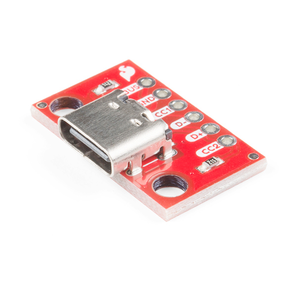
SparkFun USB-C Breakout - Horizontal
With this USB breakout you will finally be able to incorporate a USB-C connector into your projects without needing to solder each tiny SMD pad. The SparkFun USB-C Breakout supplies up to three times the power as previous USB iterations and also solves the universally frustrating dilemma of plugging a USB cable in correctly because it's reversible!
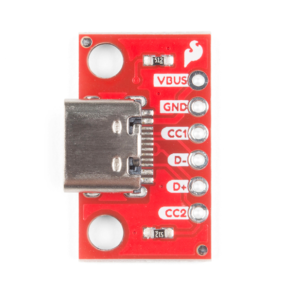
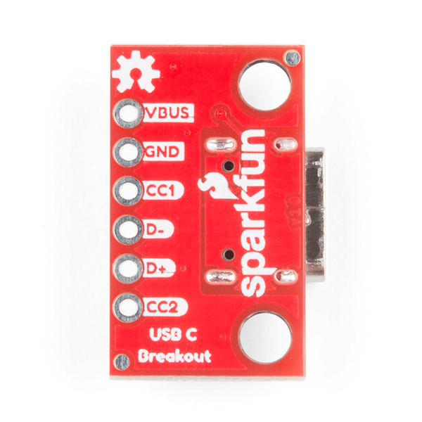
This board breaks out the USB-C connector's VBUS, GND, CC1, CC2, D+, and D- pins intro a 0.1" pitch header while providing up to a nominal 1.5A of power and up to 3A depending on the upstream device.
- Connector: USB Type-C
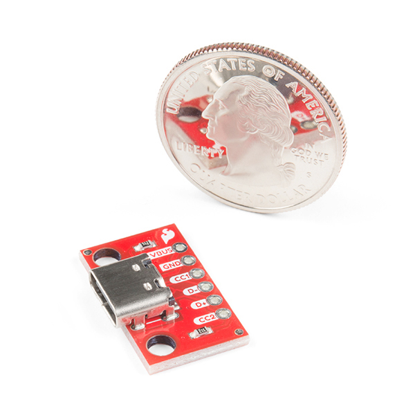
- Dimensions: 22.1mm x 14mm x 4.9mm (0.87in x 0.55in x 0.19in)
- Weight: 1.35g
SparkFun USB-C Breakout - Horizontal Product Help and Resources
Connector Basics
January 18, 2013
Connectors are a major source of confusion for people just beginning electronics. The number of different options, terms, and names of connectors can make selecting one, or finding the one you need, daunting. This article will help you get a jump on the world of connectors.
Core Skill: Soldering
This skill defines how difficult the soldering is on a particular product. It might be a couple simple solder joints, or require special reflow tools.
Skill Level: Noob - Some basic soldering is required, but it is limited to a just a few pins, basic through-hole soldering, and couple (if any) polarized components. A basic soldering iron is all you should need.
See all skill levels
Comments
Looking for answers to technical questions?
We welcome your comments and suggestions below. However, if you are looking for solutions to technical questions please see our Technical Assistance page.
Customer Reviews
4.5 out of 5
Based on 6 ratings:
1 of 1 found this helpful:
Worked for my application
I was using this to convert my wyze camera into a usb camera for a 3d printer enclosure. That way i could go directly into a raspberry pi with the data so octo pi could host the stream, and i could provide power via an external power supply. All while only using 1 cable. Wish there where 3d cad models of it so i could make a enclosure easier and more accurate then what i did. im not sure if thats really a complaint or just a nice to have but all other documentation was there. The microchip paper they link isn't the newest and it has most of the usb c spec explained in there. Not a great paper but easy enough to understand.
Handy for any project on a breadboard!
I used this on a breadboard project because I had left over wall wart 5 Volt power supplies with USB-C Connectors. Worked great and powered the project fine with no additional voltage regulation.
I use this BOB and the mini USB BOB now to power most of my projects. I did make a few BOB’s of my own. Printed the boards and populated, but frankly for the price from spark fun its not worth the time or effort.
Does what it says
I wanted to test out USB-C before sending out my boards for PCB-A. Spec said it should be a drop-in to replace an old school USB as long as I added the correct resistors. It worked great!
Speaking of PCB-A, SparkFun I will pay 10x what I currently pay if you give me a PCB-A option in the US!
Very handy breakout
I needed a quick way to add a charging connection to a battery power project, and this was the ticket


Excuse if I'm being dense in this question, but my limited understanding with USB-C is that it needs to negotiate type to work, can this board be used to provide 5v power without needing a negotiation or is there another step required to use this for providing a 5v power output?
Hi there, it sounds like you are looking for technical assistance. Please use the link in the banner above, to get started with posting a topic in our forums. Our technical support team will do their best to assist you.
That being said... if you are inquiring about the PD (power delivery) information, covered in section 3 of the datasheet/application note, we use 5.1 kΩ resistors as shown in our schematic.
What is the part number or datasheet link for the USB-C Connector on this board ?
I don't think we have a datasheet from the manufacturer as it's a "generic" USB-C connector. However, you can check out the drawing for a part number.
Unfortunate that the D+/D- lines are shorted together on the board, in a given USB-C connection only one of the pairs of lines are typically actively used (D+/D- on top a.k.a. A6-A7, or D+/D- on bottom a.k.a. B6-B7), it would be nice to be able to use the inactive pair for other purposes. I'd like to see both lines broken out with an optional on-board jumper to choose if they are shorted together or not.
I am not sure if that was a mistake (i.e. the wrong schematic got posted), but currently, the schematic shows otherwise.