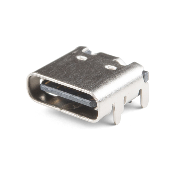
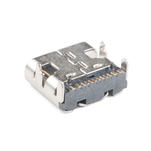
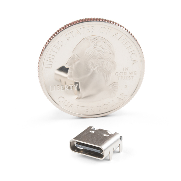
USB-C is quickly becoming more and more prominent in the maker community because, let’s be honest, who likes trying three times to insert USB into a port? This is a 16-pin, female, USB Type C connector that is commonly found in smart phones, laptops, and other newer electronics. Each USB-C connector will require PTH soldering to secure it to your board and SMD soldering to connect each of the 16 control pins.
If you are looking for an easier way to hook up a USB-C connector to your project, we do offer a breakout with 0.1" spaced, breadboard friendly pins.
USB Female Type C Connector Product Help and Resources
Core Skill: Soldering
This skill defines how difficult the soldering is on a particular product. It might be a couple simple solder joints, or require special reflow tools.
Skill Level: Competent - You will encounter surface mount components and basic SMD soldering techniques are required.
See all skill levels
Comments
Looking for answers to technical questions?
We welcome your comments and suggestions below. However, if you are looking for solutions to technical questions please see our Technical Assistance page.
Customer Reviews
No reviews yet.


The data sheet link is erroneous, as it is for a mating male connector.
The linked datasheet is actually an Application Note (AN1953) on USB-C; that is why there are references to USB-C cables.
Is there an Eagle CAD library for this part?
It is probably in our library; we use it as a production part on some of our boards.
Would it be possible to have the mechanical drawings?
The Dimensional Drawing has been added to the Documents tab!
I also wanted to get a copy of the mechanical drawing, so I did some digging, and I think I found it, or at least it should be pretty close...
I'm pretty sure is this guy, but I'd like to get a confirmation from Sparkun.
http://www.sz-fpi.com/pd.jsp?id=413#_jcp=3_83 http://12434886.s21d-12.faiusrd.com/61/ABUIABA9GAAg3pT2zwUohufO8gE.pdf