With GPS you are able to know where you are, where you're going, and how to get there anywhere on Earth within 30 seconds. This means the higher the accuracy the better! GPS Real Time Kinematics (RTK) has mastered dialing in the accuracy on their GPS modules to to just millimeters, and that's why we had to put it on this board!
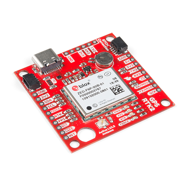
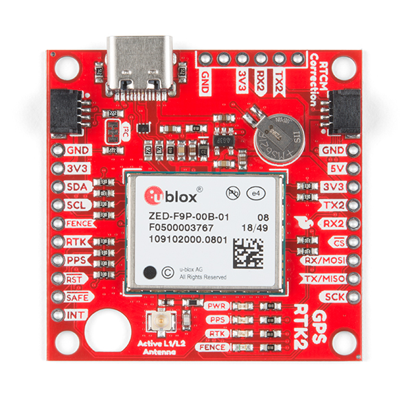
The SparkFun GPS-RTK2 raises the bar for high-precision GPS and is the latest in a line of powerful RTK boards featuring the ZED-F9P module from u-blox. The ZED-F9P is a top-of-the-line module for high accuracy GNSS and GPS location solutions including RTK that is capable of 10mm, three-dimensional accuracy. With this board, you will be able to know where your (or any object's) X, Y, and Z location is within roughly the width of your fingernail! The ZED-F9P is unique in that it is capable of both rover and base station operations. Utilizing our handy Qwiic system, no soldering is required to connect it to the rest of your system. However, we still have broken out 0.1"-spaced pins in case you prefer to use a breadboard.
We've even included a rechargeable backup battery to keep the latest module configuration and satellite data available for up to two weeks. This battery helps 'warm-start' the module decreasing the time-to-first-fix dramatically. This module features a survey-in mode allowing the module to become a base station and produce RTCM 3.x correction data.
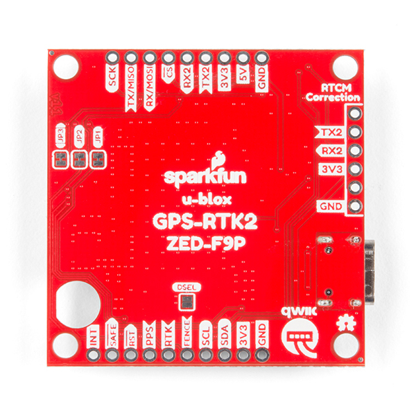
The number of configuration options of the ZED-F9P is incredible! Geofencing, variable I2C address, variable update rates, even the high precision RTK solution can be increased to 20Hz. The GPS-RTK2 even has five communications ports which are all active simultaneously: USB-C (which enumerates as a COM port), UART1 (with 3.3V TTL), UART2 for RTCM reception (with 3.3V TTL), I2C (via the two Qwiic connnectors or broken out pins), and SPI.
We've also written an extensive Arduino library for u-blox modules to make reading and controlling the GPS-RTK2 over our Qwiic Connect System easy. Leave NMEA behind! Start using a much lighter weight binary interface and give your microcontroller (and its one serial port) a break. The SparkFun Arduino library shows how to read latitude, longitude, even heading and speed over I2C without the need for constant serial polling.
Note: The I2C address of the ZED-F9P is 0x42 and is software configurable. A multiplexer/Mux is required to communicate to multiple ZED-F9P sensors on a single bus. If you need to use more than one ZED-F9P sensor consider using the Qwiic Mux Breakout.
The SparkFun Qwiic Connect System is an ecosystem of I2C sensors, actuators, shields and cables that make prototyping faster and less prone to error. All Qwiic-enabled boards use a common 1mm pitch, 4-pin JST connector. This reduces the amount of required PCB space, and polarized connections mean you can’t hook it up wrong.
The ZED-F9P GPS-RTK2 can also be automatically detected, scanned, configured, and logged using the OpenLog Artemis datalogger system. No programming, soldering, or setup required!
- This product is compatible with u-blox® PointPerfect & includes a redemption code for 1-month of unlimted access for a single device. Take your precision to the next level with the PointPerfect GNSS augmentation service.
- Concurrent reception of GPS, GLONASS, Galileo and BeiDou
- Receives both L1C/A and L2C bands
- Voltage: 5V or 3.3V but all logic is 3.3V
- Current: 68mA - 130mA (varies with constellations and tracking state)
- Time to First Fix: 25s (cold), 2s (hot)
- Max Navigation Rate:
- PVT (basic location over UBX binary protocol) - 25Hz
- RTK - 20Hz
- Raw - 25Hz
- Horizontal Position Accuracy:
- 2.5m without RTK
- 0.010m with RTK
- Max Altitude: 50km (31 miles)
- Max Velocity: 500m/s (1118mph)
- Weight: 6.8g
- Dimensions: 43.5mm x 43.2mm (1.71in x 1.7in)
- 2x Qwiic Connectors
- Schematic
- Mounting Holes and Dimension
- Eagle Files
- Hookup Guide
- Datasheet (ZED-F9P)
- UBX and NMEA Protocol Manual (ZED-F9P)
- Integration Manual (ZED-F9P)
- Product Summary (ZED-F9P)
- Release Notes - FW1.00 (ZED-F9P)
- Example RTCM output from the ZED-F9P
- u-blox ECCN
- Arduino Library - v3
- GitHub
SparkFun GPS-RTK2 Board - ZED-F9P (Qwiic) Product Help and Resources
What is GPS RTK?
September 14, 2018
Learn about the latest generation of GPS and GNSS receivers to get 14mm positional accuracy!
How to Upgrade Firmware of a u-blox GNSS Receiver
March 26, 2021
A few steps and you'll upgrade to the latest features on a u-blox GNSS receiver.
GPS-RTK2 Hookup Guide
January 14, 2019
Get precision down to the diameter of a dime with the new ZED-F9P from u-blox.
Getting Started with U-Center for u-blox
September 13, 2018
Learn the tips and tricks to use the u-blox software tool to configure your GPS receiver.
Setting up a Rover Base RTK System
October 14, 2020
Getting GNSS RTCM correction data from a base to a rover is easy with a serial telemetry radio! We'll show you how to get your high precision RTK GNSS system setup and running.
How to Build a DIY GNSS Reference Station
October 15, 2020
Learn how to affix a GNSS antenna, use PPP to get its ECEF coordinates and then broadcast your own RTCM data over the internet and cellular using NTRIP to increase rover reception to 10km!
GNSS Correction Data Receiver (NEO-D9S) Hookup Guide
October 27, 2022
Add GNSS correction data to your high precision GNSS (HPG) receiver with the u-blox NEO-D9S! This tutorial will get you started with the ZED-F9P, NEO-D9S, and the ESP32 IoT RedBoard.
Getting Started with u-blox Thingstream and PointPerfect
January 23, 2023
Interested in high precision GNSS without setting up a base station?
Core Skill: Programming
If a board needs code or communicates somehow, you're going to need to know how to program or interface with it. The programming skill is all about communication and code.
Skill Level: Competent - The toolchain for programming is a bit more complex and will examples may not be explicitly provided for you. You will be required to have a fundamental knowledge of programming and be required to provide your own code. You may need to modify existing libraries or code to work with your specific hardware. Sensor and hardware interfaces will be SPI or I2C.
See all skill levels
Core Skill: Electrical Prototyping
If it requires power, you need to know how much, what all the pins do, and how to hook it up. You may need to reference datasheets, schematics, and know the ins and outs of electronics.
Skill Level: Rookie - You may be required to know a bit more about the component, such as orientation, or how to hook it up, in addition to power requirements. You will need to understand polarized components.
See all skill levels
Comments
Looking for answers to technical questions?
We welcome your comments and suggestions below. However, if you are looking for solutions to technical questions please see our Technical Assistance page.
Customer Reviews
4.4 out of 5
Based on 21 ratings:
2 of 2 found this helpful:
Great Product - Very Statisfied!
I purchased two of these; one to act as a base station sending correction data to a rover. I am getting 14mm accuracy (estimated).
Only IMHO, the software library is missing some functionality and it really should be able to be used with less polling...more interrupt driven. Also, there are a couple of items in the Hookup Guide that could use some clarification.
6 of 6 found this helpful:
Working (great) as advertised
We bought 2 of the ZED-F9P modules from SparkFun, one for a base station and the other for a rover. After setup, both are working great for us, providing Fixed RTCM corrections. We will probably buy a third unit for fixed installation on a UAV. We are using SNIP to push out the base station RTCM corrections and our rover uses Android app NTRIP Client to pull those in from RTK2go.com:2101 (if you have a static IP you can forego the RTK2go layer).
Our rover is using a SparkFun BlueSMIRF bluetooth module, however we recommend following the SparkFun instructions in the GPS-RTK2 hookup guide that suggests using the Bluetooth Mate. The BlueSMIRF and Mate both perform the same functions however the pinout on the Mate lines up directly to the ZED-F9P pins and makes life easier.
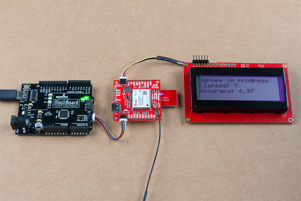
For our base station we are also using a Redboard (Qwiic) and SparkFun 20x4 SerLCD which helps in monitoring the RTCM output status at a quick glance (without using u-center). We also have tested using Ublox' u-center app which is an important (for us) step in testing and customization of the modules. On a side-note, when connecting to or disconnecting from the Qwiic connectors attached to the board, don't go Rambo on them and think you can yank them around. We accidentally ripped one of the Qwiic connectors out by not following this advice. You may not need both connectors and can daisy-chain off of one if necessary.
We are able to obtain a fix using Survey-In without a problem. Note that the longer you can leave it in Survey-In mode the more accuracy you'll obtain. If you are going to leave the base unit in a fixed spot we'd recommend leaving this in Survey-In mode for at least 4-6 hours, the longer the better (24 hours?). Once you have obtained your Fixed Lat/Lng/Height you can put the unit in Fixed Mode with those X,Y,Z coordinates.
We still need to add a radio module onto our base unit so that we can get rid of the USB wire between our laptop and the base unit (so we can mount this outside permanently), however that is a pretty straightforward step. Another addition may be a solar charger to trickle charge battery(s) on the base, eliminating all cords to the base making it self-sufficient.
The initial learning curve can seem somewhat daunting, however Google is your friend. Watch YouTube videos on RTCM if you don't have at least a basic understanding of the topic. U-Blox has many detailed instruction manuals around the F9P but also for u-Center which is an integral part of this system. SparkFun has many manuals as well which are VERY helpful in getting this setup and running. If you aren't afraid of doing a little bit of reading and research you should be able to get a base station and rover up and running just like we did.
1 of 1 found this helpful:
We have successfully tested and made to work in RTK mode. The performance is excellent. We could get position fixing accuracies within 15 mm. For the time being we made communication link using RF amplifiers and using GSM network still to explore. Of course, lack of literature on F9 device is a hurdel yet.
1 of 1 found this helpful:
Substantial improvement over M8P
Wicked-fast TTFF, and the input sensitivity with the recommended antenna is noticeably improved over my M8P-based setup (even with the newest firmware). I can now get a decent fix indoors!
Would I love a smaller board? Sure. But for the enhanced performance, I'll find room for it.
1 of 1 found this helpful:
Pretty Good
It's early in the development cycle, so the device and the doc's for it have a few rough edges still. It also does L2 GPS data slightly differently than the survey gear does. That can lead to issues with a whole range of support and analysis software. Mine decided to move 40 M over night. I checked and the antenna is still right where it was yesterday .....The NetR9 running next to it had no issues ...
1 of 6 found this helpful:
Trying hard to gett this to work in RTK mode with no luck
Board is easy to set up but near impossible to get to work. I baught 2 of them one for base and one for rover and although i did everything correct i can not rover to receive the RTCM data from the base. Documentation is mediocre.
Do yourself a favor and stay away from this board.
Works but...
The system seems very accurate. But it also is less than easy to set up.
Hardware: Two SparkFun "GPS-RTK2 Board - ZED-F9P (Qwiic)" boards, one for use as a BASE and one as a ROVER. One each Sparkfun Redboard Qwicc. A few Qwicc connector cables (only really needed 1). Two 900 mhz Digi Xbee radios Running DigiMesh. I bought 3 plus serial boards from DigiKey for $99 (Digi-XBee Mesh Kit on DigiKey "XBEE-PRO 900HP DIGIMESH KIT (US/". DigiKey part number "602-1843-ND"). For the price I couldn't turn the kit down. Two plugs and attached wiring to connect the radios. Two UBLOX antenna. Although available from SparkFun I bought them (DigiKey part number 672-ANN-MB-00-00-ND) from DigiKey, mainly because they had longer antenna leads. A 33 ft antenna extension cable from Amazon. I don't have it yet and probably don't need it, but I may want to mount the Base on my roof. Two 4.5 inch round electrical box covers for use as ground planes.
Software: Set the radios 230400 baud. Used "Example3_StartRTCMBase" as the basic setup for the Base after changing the output port for all the messages to UART 2 and the baud rate for that port to 230400, "myGPS.setSerialRate(230400, COM_PORT_UART2)". Ended up running "In-Survey" for a couple hours instead of 5 minutes. That got the uncertainty down pretty low. May run it longer to see what happens. The docs say up to 1 day may be desirable. Used "Example8 _GetHighPrecisionAndAccuracy" as the basic setup for the Rover.
Some issues: Pretty much the main issue is the GPS board needs to be reset almost every time you make a change. I used "Example12_FactoryDefault_I2C". When you load the sketch, depending on what you were running befor, you may need to disconnect the GPS from the RedBoard (I2C) and/or you may need to cycle the power on the GPS.
Making heads or tails of the U-Center software is more fun than I can tell you. :)
Stick with it and you'll get good results.
Very accurate and easy for implement
GPS RTK2 this board is easy to implement and It's performance quite good/accurate. Yes it quick to recapture the location after it sleep. So far, we are satisfied.
Question
It seems to interface with gpsd in Linux but should I have gotten an antenna. I hooked a wifi passive antenna to the UFL connector. No satellites responded; at least non-intelligible. Hopefully this is an oversight on my part and not a defective unit.
Please tell me what more I will need to get this unit to respond. I have read good things about this unit.
Thank you.
Unfortunately WiFi is in a different frequency band than GPS/GNSS and a WiFi antenna will not work with these modules. You need a GPS antenna like part number GPS-14986 for this to get any signal. Please see the hookup guide for more information on antennas and if you have any more questions, check out our technical assistance page.
Great receiver.
The F9P picks up dozens of signals with a good antenna attached. Update your firmware quarterly. Ideal for streaming data to galmon.eu for GNSS monitoring. Adding an ESP32 for NTRIP from CRTN/UNAVCO.
Great Learning Experience
Great product for learning all about GPS Real Time Kinematics (RTK). It took me a few nights to go through the tutors and get it up running the way I wanted. It was amazing to see it track 30 satellites all the time. And with the backup battery it cool to watch it acquire satellites and lock in a position in less than 30 seconds. The closest RTCM source is 300 miles away that I could find, so I could lock down to about a meter of accuracy which is great, but I am hoping for more. It looks like I will have to buy a second unit to get the accuracy that I want. Just not in the budget yet. The U-Center software is great and lets you do all kids of cool stuff to understand what is going on inside this little red PCB. U-Center is like a great piece of test gear to evaluate GPS. At first the it can be overwhelming because of what you can change and play with but hang in there. Hope to update this when I get a better RTK source.
Pretty good indeed!
Thanks for the product. Really satisfied with the product. However, I would like to see some ROS support from your github page. There are supports from ublox but not for this specific device. Communication with the device with rtcm enabled is a little difficult to handle in ROS. Also, one should try to buy 2 units together ( & accesories to communicate in between) which is the ultimate goal of real time kinematics support.
Works Fantastic
No problems. It started right up receiving 46 satellites and the clock started improvements right away. A fantastic board with access to all the important pins.
L1/L2 has me back in the game
I've been running Sparkfun GPS boards for years for both personal and government projects. Analysis continues to get easier. When the previous GPS-RTK board came out I jumped for it... antenna on roof... local CORS station for a reference... RTKLIB post-processing. By averaging weeks of data I got to a sub-cm solution for my roof antenna. Still... it was a differential measurement with a 6 km baseline. Now, however, with the F9P and the NTRIP stream of SSR corrections I see a real time solution of roughly 2-3 cm. Your Hookup Guide was a great help to getting it up and running quickly. Now its time to dive back into RTKLIB (demo5 from rtkexplorer.com) to reach a PPP absolute position in post-processing and see what happens.
F9P moving base RTK is impressive
The F9P gave me the relative position between two moving objects using patch antennae and the RELPOSNED message.
Perfect RTK GPS Module
Works perfect, I use a radio to supply RTCM3 via RS232 (Via Serial to TTL Adaptor). Setup the baud rate and perfect RTK fixed postion.
Super board, until it died
ZED-F9P is plug and play board, simple to use and does not need any setting adjustments prior to first use. I was using it together with Bluetooth Mate Silver for RTK correction. BT Mate was attached to the board like described in GPS-RTK2 Hookup Guide. Assumingy in one moment there was a shortcut between BT Mate and the ZED-F9P module (in the section where there are jumpers on ZED-F9P) and I was not been able to connect to the ZED-F9P module again. I also noticed that RTK led is barely on. I reccomend to put inslulating tape between BT mate and ZED-F9P board. I would like to buy a new one, but the price is just not that attractive.
Good product!
This product has many terminals and can be used conveniently. It is also nice to provide design information. Very easy to use. I want to buy more, so I want to increase production quickly.
Amazing capability
I have been using this in static mode and post-processing the data with RTKLIB. While I have not yet been able to verify the absolute accuracy of a fix with integer ambiguity resolution after post-processing, I did get a fix with 1800 points on 1 second epochs while on a hilltop that put all points within a 5mm circle. This would be survey grade accuracy for about 2% of the cost of a survey grade system. Have not yet attempted real-time kinematic operation yet.
Is good
Well module is everything you need to prototype, I wish if can add a TTL level shifter in UART terminal because some radiomodens work to 5V and module justt support 3.3 V levels
Overachiever
Now its easier to track my wife location

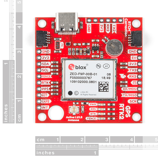
Just purchased this board and cant wait to get my hands on it! Wondering if you have any drawings with dimensions? I want to design and 3D print a case to protect my $220 investment. (look for it on Thingiverse in a week or so after my board/antenna arrives) Plan to use the ZED-F9P to survey a 4.4 acre property of mine and aid in generating a topographic map. The land is fairly flat and collects quite a bit of water in spots. We hope to build a home on the property soon and even dig a pond. With a topo map in hand I can use my tractor and site level to sculpt the land as needed to fix drainage and properly locate our pond/ house.
Neat project! I've posted mounting hole and board dimensions. Sorry I don't have a full 3D render but the eagle files are available if you want to import into Fusion 360.
Your drawing will do just fine! Thanks for posting!
Not to be a negative Nancy, I love SparkFun. I wish they would sell the official uBlox Application Boards too. The uBlox C099-F9P (https://www.u-blox.com/en/product/c099-f9p-application-board) is so more feature rich and such a better buy for only $30 more on DigiKey.
Thumbs up dude. I went ahead and ordered the application board instead, for testing. In the future, I'll probably order the sparkfun modules as well, due to their smaller footprint.
Arrghh ..... I wish I had known you were so close to releasing this board and would have ordered from SparkFun instead of the ArduSimple project .... which won't be to my house until February! No matter ... Congratulations and I'm very glad you have added this to them list of SparkFun products! I've already told my co-workers to look at this unit!
On another point ... you don't seem to have any antenna available here on SparkFun which cover both the L1 and L2 band. Is that something you're going to fix in the next week or so .... that way I won't make another purchasing blunder ;-)
Oh ... one with a stable and well known phase center would really rock too
Thanks!
Check out the GNSS Multi-Band Magnetic Mount Antenna - 5m (SMA).
Nate, Has anyone done example code with the recommended qwiic lcd, bluetooth(SparkFun Bluetooth Mate Gold WRL-12580), this module and arduino to be base station, with the same pieces as a rover? I am not close enough to a correction center, so got 2 sets of the hardware listed, and can see bluetooth output to a phone for RCTM, but getting a second unit with a bluetooth to connect, and use the data is not working.
Also when the LCD is set up is it possible for it to read out the current GPS coordinates instead of or along with the RCTM transmitting?
Thank you
Just a quick note that the current consumption value of ~35 mA noted in "Features" is incorrect. According to the ZED-F9P data sheet, the current draw can range from approximately 68 mA (GPS + tracking) to 130 mA (GPS+GLO+GAL+BDS + acquisition).
I want to buy this board but I'm a novice, so here are a few questions. Is the antenna included in this product? Does the board record GNSS signal when it connects to power and antenna?
Nope. Please check out the GPS-RTK2 Hookup Guide .
Could this board be connected to a SparkFun RFID Evaluation Shield - 13.56MHz please?
Hi there, it sounds like you are looking for technical assistance. Please use the link in the banner above, to get started with posting a topic in our forums. Our technical support team will do their best to assist you.
Does anyone have a foolproof way to get the Ublox usb to serial driver working in Windows 7 x64? It works without any effort on my part on my desktop computer but on my laptop I cannot install the correct driver. I've tried Ublox's downloads and countless other forum/blog suggestions. Sometimes it looks good but there's no data.
Just to be sure have you modified the drivers from the GNSS Location Sensor to a serial port? More info here.
I purchase this product with antenna, SMA-u.fla cable and ground table. I use this with tera term and u-center. But it have not given any value. In hook up guide, rtk led will high when this module isn't fixed mode. But my purchase one's led is low... I think it is broken down. Can I exchange this product?
Hi there, it sounds like you are looking for technical assistance. Please use the link in the banner above, to get started with posting a topic in our forums. Our technical support team will do their best to assist you. (As a note, it will probably be useful to provide pictures of your setup/wiring for the TS team.)
Can someone say whether the board has a pin for EXTINT from the F9P chip? It's just to sense the state of a switch so the F9P can log an event when the switch is flipped. It's commonly used in photogrammetry applications with a camera flash shoe to log when a photo was taken. I looked closely at the pictures but couldn't find it...
The INT pin on the board (bottom left) is pretty versatile and can be programmed via ucenter to go high (or go low) when various conditions are met. Checkout the ucenter software and the F9P guides for more info on the capabilities of the pin. If those don't answer your question please let me know.
It's really great to see SparkFun leading the development of boards with the new u-blox modules!
However, I'm curious to know the reasons behind only including a u.FL connector. Given the available real-estate, it appears the board could have accommodated the pads for an edge-launch SMA connector. This would have had the benefit of providing users with the option for a more direct and reliable antenna connection. I know I constantly worry about the fragile u.FL cables/connectors.
Good question. There's a variety of reasons:
You can certainly damage this board and any other board with vibration/shock/pond water. After years of messing about with antenna connectors I usually cause some other damage (or when bees covering your humidity sensor with wax) long before a U.FL antenna bites the dust.
I'm glad it has the u.FL connector as it makes it easier to swap out for other, similar boards which also have u.FL. Other boards that have the SMA connector onboard (e.g. CSG Shop) limit your packaging options.
Thanks for the detailed reply, Nate! I picked up the board from Digi-Key and can't wait to start testing!
Also, super cool beehive project! :)
If I'm planning to use this device on a moving vehicle, how does the vehicle's speed affect both the precision and refresh rate (20Hz), say at 40mph, or 50mph? My project requires a precision of 3cm and 20Hz refresh rate at 40-50mph.
The max velocity of the ZED-F9P is 500m/s or 1120mph. The board should perform just fine at 50mph.
The default "Dynamic Platform Model" is Portable, which has a max horizontal velocity of 310 m/s and 50 m/s vertical. uBlox supports other modes as well, which can be set via uCenter, or dynamically using the CFG-NAVSPG-DYNMODEL command. The supported modes are: Portable, Stationary, Pedestrian, Automotive, At Sea, three Airborne modes and a wrist mode. The different modes determine the filtering settings. 500 m/s is only supported in the Airborne <4g mode.
Section 3.1.7.1, page 20: https://www.u-blox.com/sites/default/files/ZED-F9P_IntegrationManual_%28UBX-18010802%29.pdf
Thanks Nate for your reply. Can you advise if velocity affects my target precision of 3cm, and how?
Precision is rated at max velocity so you should not have precision degradation at 50mph.
Hi Nate,
One quick question please: How many bytes are contained in an RTCM transmission from a base to a rover?
Thank you, Nir
Hi Nir - It's a bit buried but you can view example RTCM output from the ZED-F9P (it's listed at the end of the hookup guide). This single transmission is 509 bytes. Whether that increases or decreases between transmissions I am not sure. I believe every 10 seconds the packet is larger due to the RTCM_1230 message being sent.
The number of bytes is a function of the number of satellites in view and the number of carriers available (e.g. L1 only, or L1 & L2). Since RTCM is a binary protocol, the resultant bitrate is relatively low, on the order of low 10s of Kbps at most.
Thank you Nate. One last question: Assume I have everything working i.e base is sending correction data to the rover and rover knows exactly where it is and now I wish to upload this data to the cloud - is there way to extract this data from the rover?
I recommend our LTE shield. This should allow your rover to pull down the RTCM corrections via NTRIP over cellular. You can then use that same cellular link to push up the rover's position to whatever cloud service you'd like.
Please Please build a version of this with a SMA rather than the super fragile u.FL....
Does this module support L-Band correction services from any vendor (OmniStar, TerraStar, Atlas, etc)?
I just found a possibly appropriate antenna for use with these in GPSWorld.
Have you looked at the AGR6302/6303 antenna from Allystar? Its a magnetic mount with the following: AGR6302 is capable of receiving L1/L2 bands, and AGR6303 is capable of receiving L1/L5 bands. I think we would be interested in the 302.
Thanks in advance!
Dose the RTK (high accuracy) mode require a 2nd module as a base station? If so how dose the base station communicate with the Rover module?
Checkout the hookup guide, namely how to connect a correction source.
RTK requires a correction source. That can come from a 2nd module that is acting as a base station, or the correction data can come from a 3rd party. There's a few hundred(?) sources across the globe but you have to be within ~10km of a station for the correction data to be helpful.
How to communicate correction data from a 2nd module setup as base station to the rover? Again, this is mostly covered in the hookup guide but the short answer is cellular is probably your best bet. I recommend pulling in the RTCM bytes from the RTK2 using a micro on your choice, and then pushing those bytes over cellular using our CAT LTE board.
Does this GPS have an altitude limit (i.e. can it be used for high-altitude balloons)?
This is what happens when we stop selling RTFM stickers... ;)
Yes, the altitude limit is 50km (datasheet page 4). The velocity limit is 500m/s.
Sigh. I didn't even think to look at the docs, because in my experience these things aren't well-documented. If they mention it at all, they're rarely specific, and it seems to vary with firmware. ITAR calls for the limits to be ANDed (that is, you are restricted from going 500 m/s above 50 km, but you can go faster than that below 50 km or higher than 50 km if you're slower than 500 m/s.
Thanks for pointing it out, though. Should be enough for balloons. Not sure it's the high price, since the balloon is unlikely to need such precise positioning.
No worries! I highly recommend ublox because of their extensive documentation. They set the gold standard for readable, well documented, support docs.
I would like to know that too. I am working on a data logger for high power rocketry.
17mm precision wow!
Is SparkFun going to offer GNSS Multiband Antenna soon?
Ask and ye shall receive!
GNSS Multi-Band Magnetic Mount Antenna - 5m (SMA)
We currently carry GNSS antennas but no multiband units yet. I'm hoping to get one in stock in 4-6 weeks.
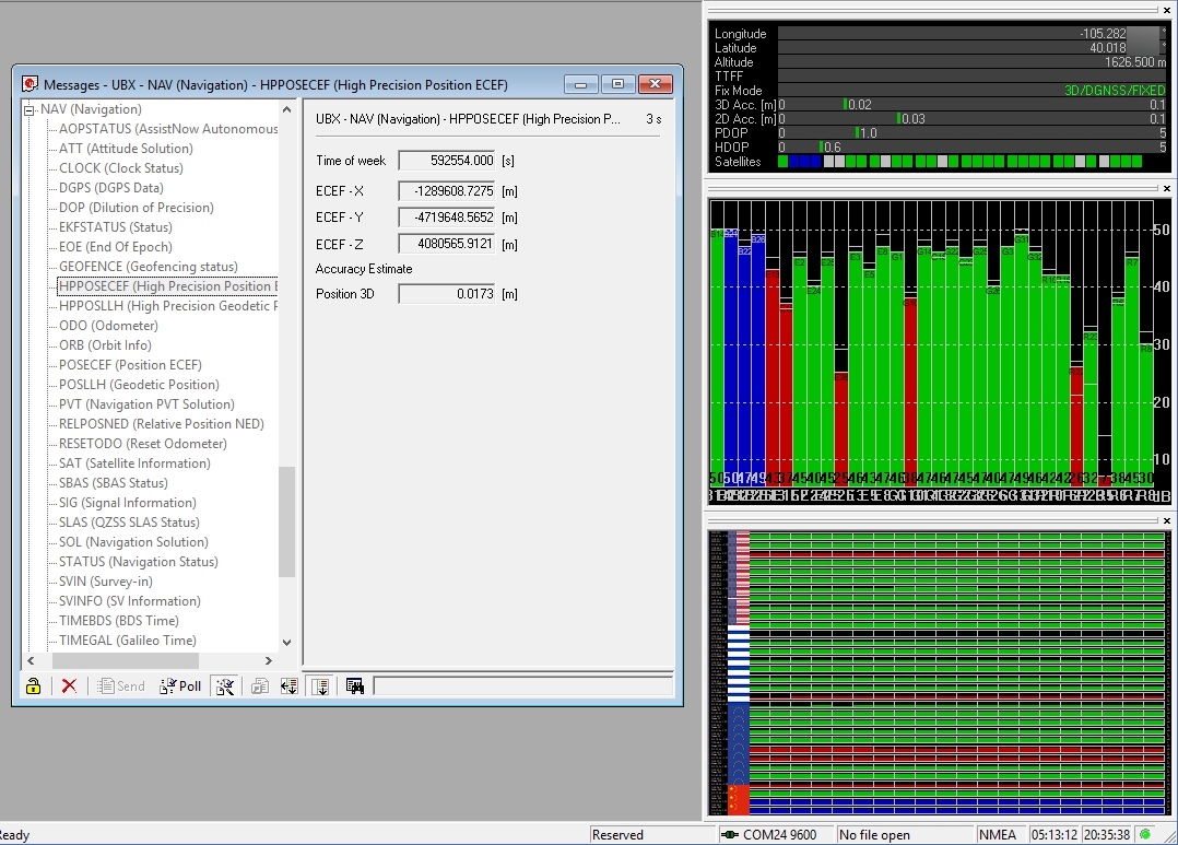
In the mean time, I've done most of my testing with the low-cost magnetic GNSS (with ground plate) and achieved the 17mm shown in the image.
(edit) We've got the L1/L2 band antennas posted now.
oops ... didn't see your reply here. I think you can get better accuracy with a better antenna ... one with a more stable phase center. Might want to try one with a CORS type survey antenna if you just want to show off how close you can get!
Remember also you can take the dual frequency raw data and feed it into OPUS to get a well surveyed ground station point. OPUS is from ngs.noaa.gov and is free to use.
You might want to talk to these guys. www.unictron.com They were in here trying to sell me large quantities of antennas but they couldn't understand I only buy antennas one at a time (Usually through Amazon or eBay or Sparkfun). But I think they would be a good fit for you. I have a direct sales guy email if you want that.
Thanks! I'll have a look.
I have a question. Is there way to connect this product without USB-C? My board's USB-C got broke that I cannot get data from it. What else can I do for getting gnss data from this board? Thanks a lot in advance.
You can communicate over serial, I2C and SPI. We've written a powerful library to make using the I2C interface easy to use from a microcontroller.
The USB-C connector on the ZED-F9P is good for configuration and for getting data, but it's not really meant to be embedded.