SparkFun Buck-Boost Converter
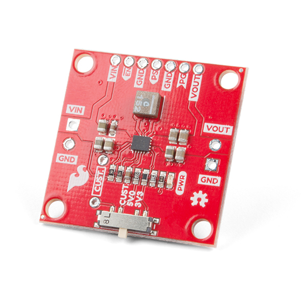
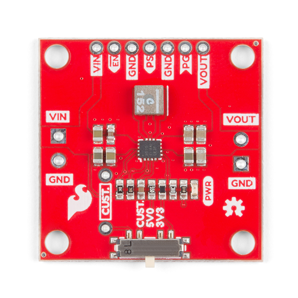
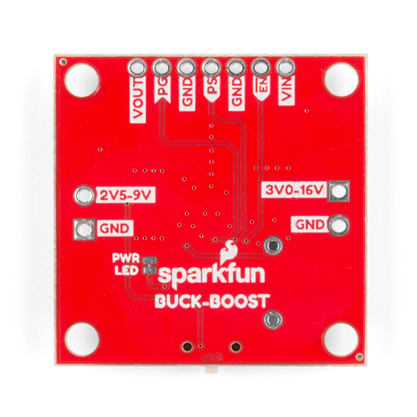
The SparkFun Buck-Boost Converter is a handy power accessory board that allows you to fine tune the amount of power your project receives. This converter can take an input voltage of anywhere from 3-16V which can then be regulated to an output voltage between 2.5-9V. With the switch on the bottom of the board, you can set the common output voltages of 3.3V and 5V, but we've also added a custom setting that allows you to solder a resistor based on your custom voltage needs. The GPIO pins have also been broken out along the top of the board for even more control!
In addition to the voltage control, the SparkFun Buck-Boost Converter uses a switching DC/DC converter, which is more efficient than a linear regulator. More efficiency means less energy is wasted in the form of heat. With built-in overtemperature protection and an optional heatsink, you can achieve up to 95% efficiency rating.
- Input voltage range of 3-16V
- Output voltage adjustable from 2.5-9V
- Three selectable output voltages: 3.3V, 5V, or custom
- GPIO broken out for additional control
- Operating die temperature range of -40 to +125°C
- Optional Heatsink
- Up to 95% Efficiency
- Overtemperature Protection
SparkFun Buck-Boost Converter Product Help and Resources
Buck-Boost Hookup Guide
May 10, 2019
This tutorial shows you how to hook up and use the SparkFun Buck-Boost board.
Core Skill: Soldering
This skill defines how difficult the soldering is on a particular product. It might be a couple simple solder joints, or require special reflow tools.
Skill Level: Noob - Some basic soldering is required, but it is limited to a just a few pins, basic through-hole soldering, and couple (if any) polarized components. A basic soldering iron is all you should need.
See all skill levels
Core Skill: Electrical Prototyping
If it requires power, you need to know how much, what all the pins do, and how to hook it up. You may need to reference datasheets, schematics, and know the ins and outs of electronics.
Skill Level: Competent - You will be required to reference a datasheet or schematic to know how to use a component. Your knowledge of a datasheet will only require basic features like power requirements, pinouts, or communications type. Also, you may need a power supply that?s greater than 12V or more than 1A worth of current.
See all skill levels
Comments
Looking for answers to technical questions?
We welcome your comments and suggestions below. However, if you are looking for solutions to technical questions please see our Technical Assistance page.
Customer Reviews
5 out of 5
Based on 2 ratings:
1 of 1 found this helpful:
This board saved my project
Having all those Sparkfun QWIIC boards available, with their libraries, saves a lot of work when developing a complex project. However, I discovered that my Redboard Turbo started to have problems when I hit my seventh QWIIC attachment. I used THIS board, the Buck-Boost converter, to beef up the 3.3 volt line on the QWIIC bus. Suddenly all those problems went away. My project already uses two of these, and I'll be getting a third one now. Good stuff.
Works as advertised
The board could be a little smaller. But it works perfectly.


This is exactly what I needed! Only issue is that its designed for screw terminals rather than pin headers.
Looks like Vin, Vout and 2x GND are duplicated on the 0.1" spaced holes on top, which you can put a header on!
Good observation, thanks you :)
I read the spec sheet. It says input range is 2V-16V but sparkfun lists the input range as 3V-16V. Any reason for this discrepancy?
Does someone have a lookup table for the required custom resistor to voltage conversion? the math on the info page is not making sense, i have no idea how to interpret the output of the formula.
Are you referring to this formula?
The output voltage is determined based on the voltage present on the feedback pin which uses a voltage divider using two resistors.
The board has a fixed 68.1 kohm resistor, which is R2, and the switch is selecting the other resistor which I refer to as R_SET. So lets say I want to set the output voltage to 5.0V, then the resistor I need to add is:
Rset (kohms) = 68.1 * (Vout / 0.8 - 1)
Rset = 68.1 * (5.0 / 0.8 - 1)
Rset = 68.1 * (6.25 - 1)
Rset = 68.1 * 5.25
Rset = 357.525 khoms
It might be challenging to get that exact resistor value, which is why on the board I went with a 365 kohm resistor. If you plug in 365 kohm for Rset and solve for Vout, you end up with around 5.09V.
The ENABLE input on the TPS63070 is active high (as evidenced by the 10k pullup), but it's labeled with the inversion bar on the silkscreen and schematic as if it was active low. I recommend removing the bar in the next revision.
But how much current can it put out??? O.K., now I see the graphs near the end of the hookup guide. Thanks, - Steve
The current rating is listed because it depends on a few factors. The board can handle up to 2A of current. The hookup guide provides a few graphs for how much current you can expect based on the input and output voltage, and if a heatsink is used.
https://cdn.sparkfun.com/assets/learn_tutorials/8/9/5/Maximum_Output_Current_Graphs.png
It would help if those graphs (or a slightly more formatted version) were included in the photo list up by the product. The first question I ask when looking at a regulator is how much current, and having to go all the way to the end of the hookup guide seems a bit excessive.
I don't think we can add those charts to the images, that is usually used specifically for images of the product itself. However, I'll see if we can get the graph linked under the Documents tab.
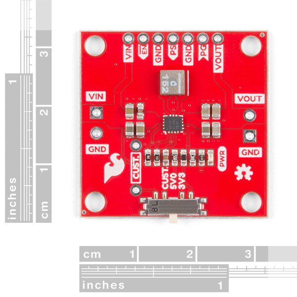
What is the Mouting hole dimension? What is the In & Out screw terminal dimension?