SparkFun Qwiic 12 Bit ADC - 4 Channel (ADS1015)
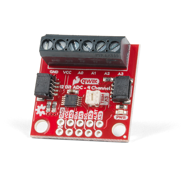
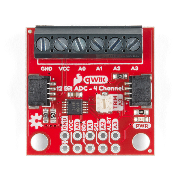
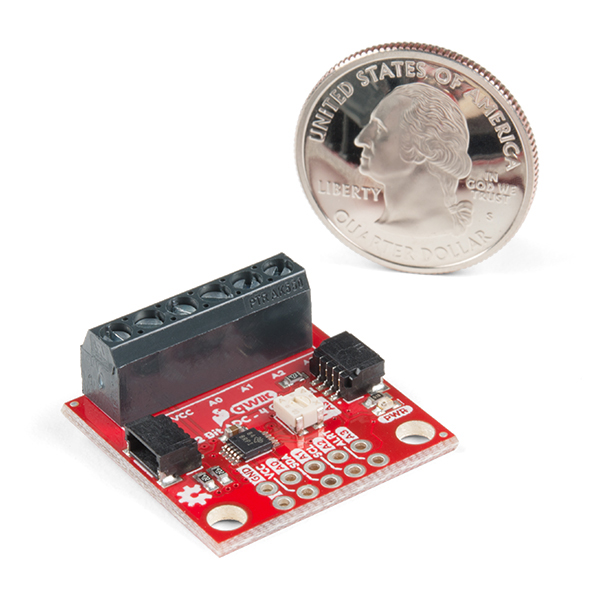
A lot of the time you just need to add more analog inputs to solve a problem. It happens. The SparkFun Qwiic 12 Bit ADC can provide four channels of I2C controlled ADC input to your Qwiic enabled project. These channels can be used as single-ended inputs, or in pairs for differential inputs. What makes this even more powerful is that it has a programmable gain amplifier that lets you "zoom in" on a very small change in analog voltage (but will still effect your input range and resolution). Utilizing our handy Qwiic system, no soldering is required to connect it to the rest of your system. However, we still have broken out 0.1"-spaced pins in case you prefer to use a breadboard.
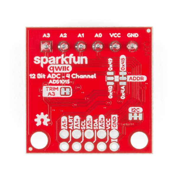
The ADS1015 uses its own internal voltage reference for measurements, but a ground and 3.3V reference are also available on the pin outs for users. This ADC board includes screw pin terminals on the four channels of input, allowing for solderless connection to voltage sources in your setup. It also has an address jumper that lets you choose one of four unique addresses (0x48, 0x49, 0x4A, 0x4B). With this, you can connect up to four of these on the same I2C bus and have sixteen channels of ADC. The maximum resolution of the converter is 12-bits in differential mode and 11-bits for single-ended inputs. Step sizes range from 125μV per count to 3mV per count depending on the full-scale range (FSR) setting.
We have included an onboard 10K trimpot connected to channel A3. This is handy for initial setup testing and can be used as a simple variable input to your project. But don't worry, we added an isolation jumper so you can use channel A3 however you'd like.
Note: The I2C address of the ADS1015 is 0x48 and is jumper selectable to 0x49, 0x4A, 0x4B. A multiplexer/Mux is required to communicate to multiple ADS1015 sensors on a single bus. If you need to use more than one ADS1015 sensor consider using the Qwiic Mux Breakout.
The SparkFun Qwiic connect system is an ecosystem of I2C sensors, actuators, shields and cables that make prototyping faster and less prone to error. All Qwiic-enabled boards use a common 1mm pitch, 4-pin JST connector. This reduces the amount of required PCB space, and polarized connections mean you can’t hook it up wrong.
- ADS1015
- Operating Voltage (VDD): 2.0V-5.5V
- (Note: When powering with a Qwiic cable, the input range is only 3.3v)
- Operating Temperature: -40°C to 125°C
- Operation Modes: Single-Shot, Continuous-Conversion (Default), and Duty Cycling
- Analog Inputs:
- Measurement Type: Single-Ended (Default)
- Input Voltage Range: GND to VDD
- Full Scale Range (FSR): ±.256V to ±6.114V (Default: 2.048V)
- Resolution:
- 12-bit (Differential) or 11-bit (Single-Ended)
- LSB size: 0.125mV - 3mV (Default: 1 mV)
- Sample Rate: 128 Hz to 3.3 kHz (Default: 1600SPS)
- Current Consumption (Typical): 150μA-200μA
- I2C Address: 0x48 (Default), 0x49, 0x4A, or 0x4B
- Operating Voltage (VDD): 2.0V-5.5V
- Screw pin terminals for solderless connection to voltage sources
- Four unique I2C addresses:
- 0x48
- 0x49
- 0x4A
- 0x4B
- 2x Qwiic connection ports
- Onboard 10K trimpot
SparkFun Qwiic 12 Bit ADC - 4 Channel (ADS1015) Product Help and Resources
Qwiic 12-Bit ADC Hookup Guide
May 23, 2019
Need to add more analog inputs for your project? Check out the Qwiic 12-bit ADC.
Core Skill: DIY
Whether it's for assembling a kit, hacking an enclosure, or creating your own parts; the DIY skill is all about knowing how to use tools and the techniques associated with them.
Skill Level: Noob - Basic assembly is required. You may need to provide your own basic tools like a screwdriver, hammer or scissors. Power tools or custom parts are not required. Instructions will be included and easy to follow. Sewing may be required, but only with included patterns.
See all skill levels
Core Skill: Programming
If a board needs code or communicates somehow, you're going to need to know how to program or interface with it. The programming skill is all about communication and code.
Skill Level: Competent - The toolchain for programming is a bit more complex and will examples may not be explicitly provided for you. You will be required to have a fundamental knowledge of programming and be required to provide your own code. You may need to modify existing libraries or code to work with your specific hardware. Sensor and hardware interfaces will be SPI or I2C.
See all skill levels
Core Skill: Electrical Prototyping
If it requires power, you need to know how much, what all the pins do, and how to hook it up. You may need to reference datasheets, schematics, and know the ins and outs of electronics.
Skill Level: Rookie - You may be required to know a bit more about the component, such as orientation, or how to hook it up, in addition to power requirements. You will need to understand polarized components.
See all skill levels
Comments
Looking for answers to technical questions?
We welcome your comments and suggestions below. However, if you are looking for solutions to technical questions please see our Technical Assistance page.
Customer Reviews
5 out of 5
Based on 1 ratings:
Excellent ADC for Raspberry Pi
I needed an ADC to monitor battery voltage for a raspberry pi project, this one was perfect. The qwiic shim made it easy to setup and start grabbing samples with a few lines of python.


Great little ADC board. It would be really useful, on a future version, if there was a way to add a jumper on the board so that you could use the onboard trimpot to scale an external voltage connected to A3.
Would be great to get a PWR LED jumper on this board!
Is the sample rate on this high enough for audio applications? What if I connect all channels to the same signal and sample in round robin?
Edit: Nope. 3300 samples per second. That's pretty good, but not anywhere near 21000
Hi #830, Sorry it took me a few days to get back to this. I see know that you've already answered your own question :) Indeed, this is more suited for reading sensors, but I suppose it really depends on what kind of application you are going for. If you want to record/playback audio sounds, then 3.3K SPS is pretty low quality, and you'd be missing out on a lot of the upper frequency range. But for measuring amplitude, I suppose this ADC could give you some ability to measure peaks and loudness. But then again, our sound detector is probably better suited for that.
If you're looking to process sound it might be worth looking into our audio boards section of the catalog
Good luck and thanks for reaching out! -Pete