SparkFun MicroMod Data Logging Carrier Board
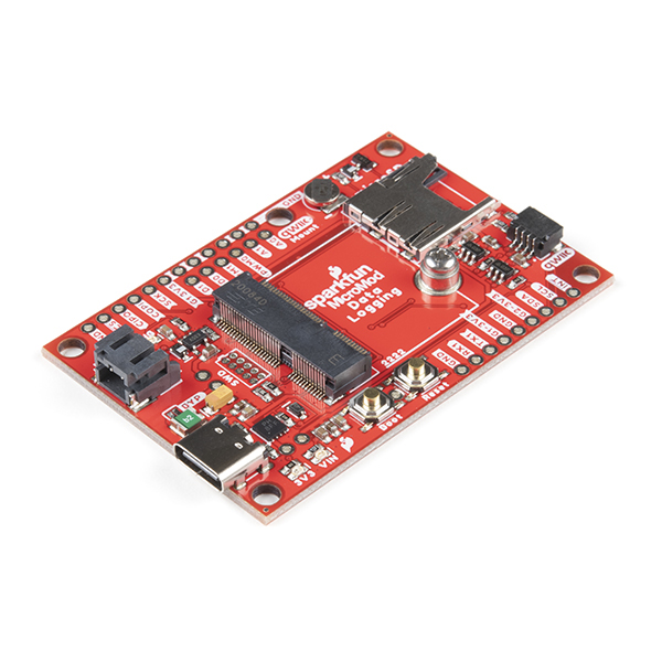
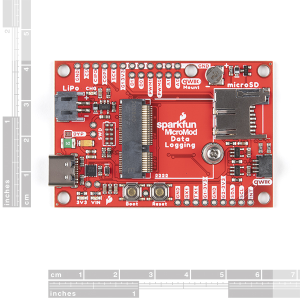
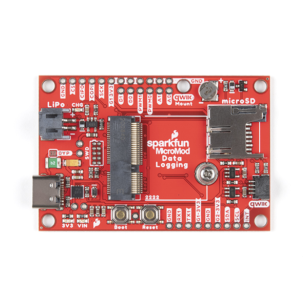
The SparkFun MicroMod Data Logging Board offers a highly customizable, low-power data logging platform using the MicroMod system allowing you to choose your own Processor to pair with the Carrier Board. The Data Logging Carrier Board breaks out connections for I2C via a Qwiic connector or standard 0.1"-spaced PTH pins along with SPI and serial UART connections for logging data from peripheral devices using those communication protocols.
The Data Logging Carrier Board allows you to control power to both the Qwiic connector on the board and a dedicated 3.3V power rail for non-Qwiic peripherals so you can pick and choose when to power the peripherals you are monitoring the data from. It also features a charging circuit for single-cell Lithium-ion batteries along with a separate RTC battery-backup circuit to maintain power to a real-time clock circuit on your Processor Board.
MicroMod is a modular interface ecosystem that connects a microcontroller “processor board” to various “carrier board” peripherals. Utilizing the M.2 standard, the MicroMod standard is designed to easily swap out processors on the fly. Pair a specialized carrier board for the project you need with your choice of compatible processor!
- M.2 MicroMod Connector
- microSD socket
- USB-C Connector
- 3.3V 1A Voltage Regulator
- Qwiic Connector
- Boot/Reset Buttons
- RTC Backup Battery & Charge Circuit
- Independent 3.3V regulators for Qwiic bus and peripheral add-ons
- Controlled by digital pins on Processor Board to enable low power sleep modes
- Phillips #0 M2.5x3mm screw included
MicroMod Data Logging Carrier Documentation:
MicroMod Documentation:
SparkFun MicroMod Data Logging Carrier Board Product Help and Resources
Getting Started with MicroMod
October 21, 2020
Dive into the world of MicroMod - a compact interface to connect a microcontroller to various peripherals via the M.2 Connector!
Designing with MicroMod
October 21, 2020
This tutorial will walk you through the specs of the MicroMod processor and carrier board as well as the basics of incorporating the MicroMod form factor into your own PCB designs!
MicroMod Data Logging Carrier Board Hookup Guide
October 21, 2020
Get started with some customizable MicroMod data logging with the Data Logging Carrier Board.
Core Skill: DIY
Whether it's for assembling a kit, hacking an enclosure, or creating your own parts; the DIY skill is all about knowing how to use tools and the techniques associated with them.
Skill Level: Noob - Basic assembly is required. You may need to provide your own basic tools like a screwdriver, hammer or scissors. Power tools or custom parts are not required. Instructions will be included and easy to follow. Sewing may be required, but only with included patterns.
See all skill levels
Core Skill: Programming
If a board needs code or communicates somehow, you're going to need to know how to program or interface with it. The programming skill is all about communication and code.
Skill Level: Competent - The toolchain for programming is a bit more complex and will examples may not be explicitly provided for you. You will be required to have a fundamental knowledge of programming and be required to provide your own code. You may need to modify existing libraries or code to work with your specific hardware. Sensor and hardware interfaces will be SPI or I2C.
See all skill levels
Core Skill: Electrical Prototyping
If it requires power, you need to know how much, what all the pins do, and how to hook it up. You may need to reference datasheets, schematics, and know the ins and outs of electronics.
Skill Level: Rookie - You may be required to know a bit more about the component, such as orientation, or how to hook it up, in addition to power requirements. You will need to understand polarized components.
See all skill levels
Comments
Looking for answers to technical questions?
We welcome your comments and suggestions below. However, if you are looking for solutions to technical questions please see our Technical Assistance page.
Customer Reviews
4 out of 5
Based on 1 ratings:
Almost perfect
I wish there was an onboard hardware RTC. Having the battery backup is nice but that requires different software for different processes, since they may or may not have an onboard RTC and it will likely be different than another. I program mostly with Circuit Python and could use the same library for any processor. The Ds 3231 RTC is available in an 8 pin soic package with built in crystal, plenty of room for one on that board.


Looking at the schematics, i can't find where SD_DAT1 and SD_DAT2 goes after it leaves the uSD card. Also, what is COPI ? Also, I used to be able to log into your technical assistance. Did you change it yet again. Why do I need to come up with a new password and account? Maybe you offer technical assistance to people that don't buy your stuff? Kinda makes me feel unloved.
Please see the latest schematic version v1.2 linked on the documents tab. The DAT1 and DAT2 lines were removed to have a pure SPI interface to the SD card (as opposed to the original SDIO).
COPI = Controller out Peripheral In. It's part of the SPI bus (along with CIPO, SCK, and CS).
We required a user/pw for any comment to reduce spam. Yes we offer technical assistance to anyone, including customers who buy from other vendors.
Nate, sorry, I'm really disappointed with this product. Aside from the totally made-up adhoc bs pin labeling (that tripped me up at 3 am in the morning) here are the real problems: 1- After install the Sparkfun board files in Arduino Board Manager - both v1.00 and v1.01, fails to retrieve the ESP32 toolchain. I was able to get things running in PlatformIO. Apparently it pulls a git tag that doesn't exist. 2 - I bought this for data logging. Currently implementations fail to provide sufficient speed with Atmel and most people have switched to STM32's. I have plenty of boards that have SPI bus to SD cards, but nothing that supports the SDIO high speed 4-lane SDMMC interface. Since this is ONLY a data logging board, I would expect it to support this, alas it does not as you have pulled DAT1 / DAT2. I could probably use the ATP carrier and wire up my own SD card, but why then have this product?
Very disappointed. I stopped buying from several companies due to this craziness, I guess that only leave that one Chinese company.
RTC Backup Battery & Charge Circuit: Which processor does the backup RTC battery support?
When will SparkFun stop putting the battery plug on the same side as the USB power plug. Makes it impossible to design a decent enclosure for any product with this flaw.
I'm super excited about the release of the MicroMod Data Logging Carrier Board.
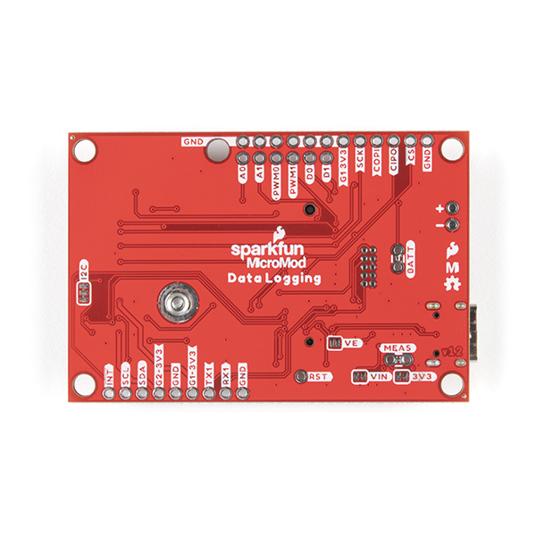
Users should be aware that the 10kΩ/20kΩ voltage divider is tied directly to VIN and will draw up to 200 uA at 6 V. As there is no jumper pad to disable the voltage divider (yet), it'll be necessary to break out an X-acto knife to cut the trace or a hot air rework station to desolder the SMD resistor(s) to reduce the quiescent draw.