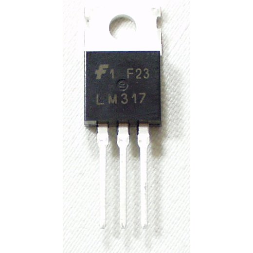
This is the LM317TG voltage regulator, a three-terminal positive regulator with a 1.2V to 37V adjustable output voltage. This adjustable regulator provides a local regulation, internal current limiting, thermal shut-down control, and safe area protection for your project. Did we mention that this guy is easy to use? It only requires two external resistors to set the output voltage. Each one of these voltage regulators can output a max current of 1.5A.
- Output Voltage: 1.2V - 37V Adjustable
- Output Current: 1.5A
- Thermal Overload Protection
- Short Circuit Protection
- Output Transistor Safe
- Floating Operation for High Voltage Applications
Voltage Regulator - Adjustable Product Help and Resources
Sound Detector Hookup Guide
February 27, 2014
The Sound Detector is a microphone with a binary output. This guide explains how it works and how you can use it in your projects.
Core Skill: Soldering
This skill defines how difficult the soldering is on a particular product. It might be a couple simple solder joints, or require special reflow tools.
Skill Level: Noob - Some basic soldering is required, but it is limited to a just a few pins, basic through-hole soldering, and couple (if any) polarized components. A basic soldering iron is all you should need.
See all skill levels
Core Skill: Electrical Prototyping
If it requires power, you need to know how much, what all the pins do, and how to hook it up. You may need to reference datasheets, schematics, and know the ins and outs of electronics.
Skill Level: Competent - You will be required to reference a datasheet or schematic to know how to use a component. Your knowledge of a datasheet will only require basic features like power requirements, pinouts, or communications type. Also, you may need a power supply that?s greater than 12V or more than 1A worth of current.
See all skill levels
Comments
Looking for answers to technical questions?
We welcome your comments and suggestions below. However, if you are looking for solutions to technical questions please see our Technical Assistance page.
Customer Reviews
No reviews yet.


Need to fix the calculator link..
Link to datasheet doesn't work. Can somebody help me with the correct link ?
I think this is it: http://www.onsemi.com/pub_link/Collateral/LM317-D.PDF
Datasheet link is a 404
The data sheet gives a minimum current draw to maintain regulation. Does anyone know what behavior to expect if this current isn't being drawn? I'm picturing some disaster like having it power an Arduino that is temporarily turned off, and then when it's turned on, awaking to 40 volts.
Now that would be a wake up call - TADA! 40V right in the input!
I'd imagine when you design your circuit - you'd design it so that no load connected to the supply, you pull at least the minimum draw somehow - lights, resistor, etc?
I know the 'LM317 Calculator' is a third party site, not run by SparkFun.
but this calculator only lets you input R1 and R1 and get output voltage, whereas I needed to input VOUT and R1, to get R2
Could I recommend this link?
http://www.reuk.co.uk/LM317-Voltage-Calculator.htm
The site isnt as pretty as the existing one, but has two calculators depending on your needs :)
1.2/R1 * (R1 + R2) = Vout
Or, the website's mathematical equivalent formula:
VOUT = 1.25 * ( 1 + R2/R1 )
Neither of them are that hard to do.
I found other lm317t calc: LM317/LM350/LM338 Calculator
I think it's best on-line calculator for 317
If I wanted this to be able to supply 9 volts, for when I have a dc jack and 9V battery connected, would it still supply 9V if I removed the jack?
No the input voltage must be 1.5v higher then the output voltage therefore you would not get 9 volts with a 9 volt battery the most you would get is 7.5 volts. Also if you wanted 9 volts from a wall wart you would need a 10.5 volt one but a 12 volt would be the best
Hey guys. I made a pretty cool tutorial demonstrating the ability to adjust the voltage of one of these by simply using a potentiometer. Check it out: http://www.instructables.com/id/Easy-Adjustable-Speed-Pocket-Fan/
can these be put in parallel if more than 1.5A is needed?
Connecting the output of 2 power sources is never really a good idea even if they are suppose to be the same value (they never are, between resistor tolerances and regulator tolerances). If you need 1.5A I would recommend finding an adjustable voltage regulator that can do 1.5A. While this is the only one we carry, try Digikey, they will probably have what you need.
Shouldn't you carry the LM337, as well, so you provide a regulator that can be used for negative voltage power supplies?
The data sheet says that the Vout is the top metal piece and then the middle pin. Whats the top piece for? I always thought it was just a screw hole.
The top piece serves 3 functions: * It provides a way to secure the IC * It is a heat sink * It is also connected to the output. The reason it's connected to the output is so it can do the best job possible of removing heat from the actual chip. If you are mounting this chip to something metal, using the screw hole, you should be sure to use a T-220 mounting kit or a mica insulator, especially if the piece of metal is grounded or electrically connected to any other part of the circuit.
Uh... datasheet says output is adjustable from 1.25 volts to 37 volts, not 25.
Just because it can go up to 37V doesn't mean you should use that much, especially without a heatsink.