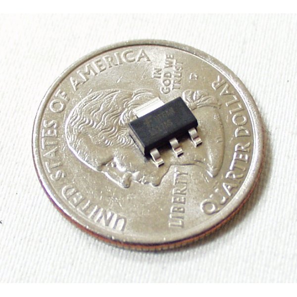
This is a 1A Adjustable SOT-223 voltage regulator capable of outputting 1.2V to 18V. The LM1117 uses the same pin-out and setup as the popular LM317 adjustable regulator, contained in a handy surface mount package. Requires two external resistors to function.
- FAN1117A
- SFE Eagle Library has this part!
- Check out our Unregulated Power Supply Tutorial
Voltage Regulator - Adjustable LM1117 SMD Product Help and Resources
Core Skill: Soldering
This skill defines how difficult the soldering is on a particular product. It might be a couple simple solder joints, or require special reflow tools.
Skill Level: Competent - You will encounter surface mount components and basic SMD soldering techniques are required.
See all skill levels
Core Skill: Electrical Prototyping
If it requires power, you need to know how much, what all the pins do, and how to hook it up. You may need to reference datasheets, schematics, and know the ins and outs of electronics.
Skill Level: Competent - You will be required to reference a datasheet or schematic to know how to use a component. Your knowledge of a datasheet will only require basic features like power requirements, pinouts, or communications type. Also, you may need a power supply that?s greater than 12V or more than 1A worth of current.
See all skill levels
Comments
Looking for answers to technical questions?
We welcome your comments and suggestions below. However, if you are looking for solutions to technical questions please see our Technical Assistance page.
Customer Reviews
5 out of 5
Based on 1 ratings:
Great Job
I'm using the LM1117 in several different configurations to evaluate various transistors and Mosfets in small experimental LED lighting circuits. Good pricing, fast delivery, excellent service by everyone. Highly recommend.


A little late, but to answer cmetom, the parameter you want is the dropout voltage, which is typically 1.1 volts @ 1 amp (1.2 V max). So to get 3.3 V @ 1 amp out with 1% regulation, you need 3.3 + 1.2 or 4.5 volts for Vin.
It looks like the output is derived from an NPN emitter, so the minimum dropout voltage you can get is one forward biased junction, which is about 0.6 volts.
So no, you can't get 3.3 volts from 3.7 volts in.
So, for 5 volts output voltage, minimum input voltage must be 6.2 right?
For the lm1117 sot-223 package:
"Tab is Vout" and "OUT" pins have 0 Ohms resistance between them.
Can this step a voltage up to 5v from 3.7v?
How do you program this to output 5v?
The datasheet shows an example schematic with two resistors, R1 and R2. You'll need to choose the values of these resistors to produce your desired output voltage. This part is electrically similar to the LM317 regulator, so you can use an online calculator such as: http://www.reuk.co.uk/LM317-Voltage-Calculator.htm to tell you the proper values.
i have UBW32 board, it has same type of part,(im not sure is it exactly LM1117 or not) but sot223..i measured now voltage on tab and on middle out leg, they were same....and on the schematic of UBW32 tab is not connected anywhere...so i guess ur fine
ok I can now confirm after making my pcb that the sfe library part for this is wrong. The output tab is not connected. Now I have a regulator with no connected output. I mistakenly thought the 3rd terminal would be output (because the datasheet is totally unclear for the smd part) but it is just the same as the input voltage.
awesome now I have a whole bunch of pcbs to mod!!!!
The library schematic symbol only shows three pins: in, out and GND but the app notes show four pins for the SMD version:
in, out, VOut and GND. I assume Vout and Out are the same thing?
Also when I connect the device in Eagle schematic I get an error that there are two pins labeled Out (but only one connected and I can't see the other pin).
In the PCB layout I can see the big tab that represents the point called "Vout" in the app notes but I am not sure if I should be connecting something to this?
Maybe I'm not looking in the right place, but I couldn't find the answer in the datasheet:
How low can the Vin be in relation to Vout?
Specifically, can this regulator chop 3.7 volts down to 3.3?
With this voltage regulator can i get 5 volts output with 5 volts input?