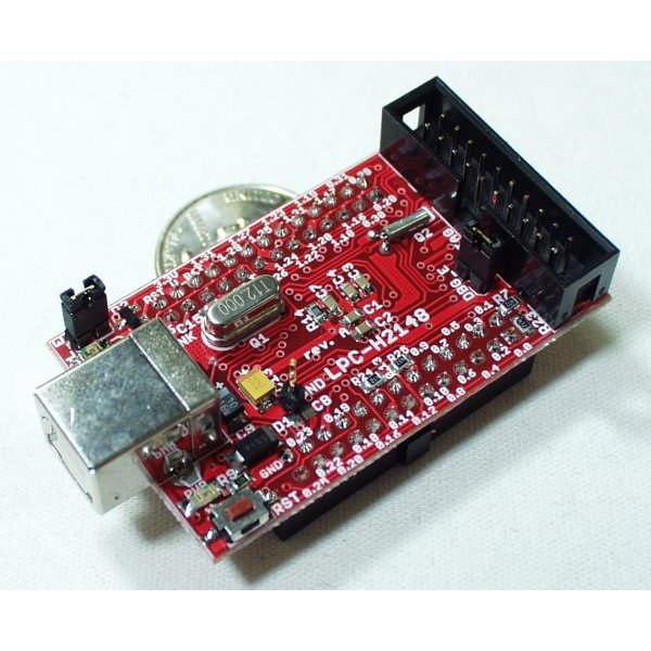
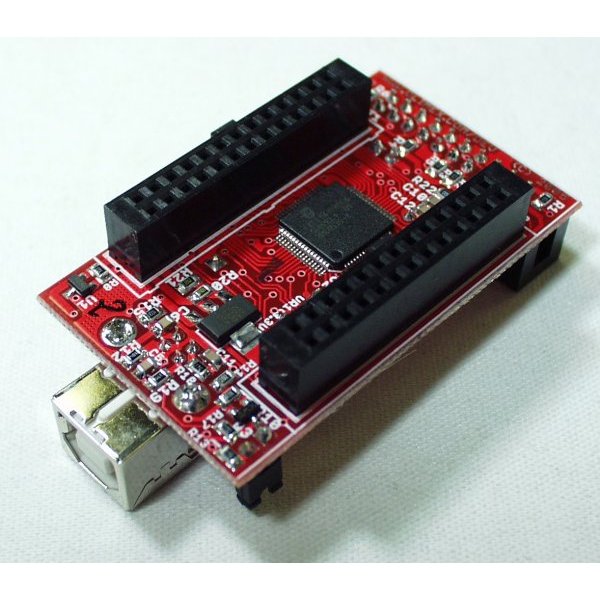
Header board for LPC2148
Small header board for the LPC2148 IC.
LPC2148 16/32 bit ARM7TDMI-S with 512K Bytes Program Flash, 42K Bytes RAM, USB 2.0, RTC, 10 bit ADC 2.44 uS, 2x UARTs, 2x I2C, SPI, 2x 32bit TIMERS, 6x PWM, 8x CCR, 1x DAC, WDT, 5V tolerant I/O, up to 60MHz operation * Standard JTAG connector with ARM 2x10 pin layout for programming/debugging with ARM-JTAG * Perfect solution for developing USB peripherials * USB connector, USB link LED * Status LED * Power supply LED * On board voltage regulator 3.3V with up to 800mA current * Single power supply: takes power from USB or extension socket pin * Power supply LED * Power supply filtering capacitor * RESET circuit * RESET button * 12MHz crystal on socket * 32.768kHz crystal and RTC backup battery connector * Extension headers for all uC ports * PCB: FR-4, 1.5 mm (0.062"), green soldermask, white silkscreen component print * Distance between the Extension headers: 25.4 mm (1")
Documents****:
- MCU:
- 2.54"x1.33" (64.5mmx33.8mm)
Header board for LPC2148 Product Help and Resources
Core Skill: Programming
If a board needs code or communicates somehow, you're going to need to know how to program or interface with it. The programming skill is all about communication and code.
Skill Level: Competent - The toolchain for programming is a bit more complex and will examples may not be explicitly provided for you. You will be required to have a fundamental knowledge of programming and be required to provide your own code. You may need to modify existing libraries or code to work with your specific hardware. Sensor and hardware interfaces will be SPI or I2C.
See all skill levels
Core Skill: Electrical Prototyping
If it requires power, you need to know how much, what all the pins do, and how to hook it up. You may need to reference datasheets, schematics, and know the ins and outs of electronics.
Skill Level: Noob - You don't need to reference a datasheet, but you will need to know basic power requirements.
See all skill levels
Comments
Looking for answers to technical questions?
We welcome your comments and suggestions below. However, if you are looking for solutions to technical questions please see our Technical Assistance page.
Customer Reviews
No reviews yet.


I've written a tutorial on how to program the LPC2148 over USB from Windows, Linux, and Mac at: https://sites.google.com/a/eng.ucsd.edu/ece30/lab-1
I wrote a USB bootloader that acts as a USB mass storage device (like a flash drive), so it is compatible with all operating systems without having to install any drivers. You program the board by copying the binary file to the block device using 'dd'. The blinky project contains a Makefile which contains targets that automate the programming process. I borrowed the idea from this sparkfun tutorial: http://www.sparkfun.com/tutorials/94. My platform addresses several shortcomings in Sparkfun's implementation:
- does not require an SD card
- works on windows, linux, and mac. The SF implementation only works on Windows because Windows' FAT driver writes blocks to sequential logical block addresses. If you try to copy a binary file onto the device from linux, it won't work, because the linux FAT driver scatters the file all across the device, rendering the binary useless. My approach is to treat the LPC2148 as a raw block device, and use 'dd' to write the binary to flash, which ensures that the binary shows up at a specific place in memory without being fragmented.
- provide a serial connection over USB through a firmware library 'usbser' that makes the LPC2148 look like a virtual COM port, so that you can read and write to it from a serial console. All three operating systems already contain drivers that support virtual COM ports.
The only catch with this bootloader is that you first have to load it onto the device using the Philips-provided on-chip serial bootloader before you can program it over USB.
USB , ARM7 Olimex /Atmel EVB 65KB SRAM , 256Flash ,64pin chip $45 .
The LPC2xxx version probably sacrifices SRAM (it has 48K ) for 512 Flash , else they are similar .
Hi. Can someone tell me if I can use this board without a JTAG programmer, like can I bootload it off USB or something?
Thanks
Ps. I ask this because I dont really want to buy a JTAG.
Yes indeed. How to program the LPC2148 without a JTAG programmer: http://ieee.ucsd.edu/news/item.php?id=144
The dimensions listed on this page are wrong. If I'd paid more attention, I would have gotten a project case.
The dimensions listed on this page include the extra distance that the USB-B connector protrudes off the end of the board.
The dimensions on the Olimex website (2270mils*1330mils) are the dimensions of the PCB without the USB connector sticking off the end of the board.
Hope this clarifies things a bit.
So what are the exact dimensions? The Olimex website says 2270 * 1330 mils which is almost the same...
Thanks!
Hi,
2270 mils = 2.27 inches = 57.7mm.
1330 mils = 1.33 inches = 33.8mm.
The longer dimension (2.54", 64.5mm) in the product description is wrong.
Hope this helps.