SparkFun RJ45 Breakout
RJ45 connectors are the kind that are used for Ethernet jacks, but they make great general purpose connectors when you need a lot of conductors. This is a small PCB that brings out the pins of the RJ45 connector to an in-line 0.1" footprint. Use with break-away headers for breadboarding or create your own RJ45 cable. Check the related items for Ethernet cable and connectors to go with it!
We used these connectors extensively in the Sound Squid demo!
Note: This is the PCB only - You can get the specific RJ45 8-Pin Connector here or in the Hookup Accessories below!
- 0.7x0.8"
SparkFun RJ45 Breakout Product Help and Resources
Core Skill: Soldering
This skill defines how difficult the soldering is on a particular product. It might be a couple simple solder joints, or require special reflow tools.
Skill Level: Noob - Some basic soldering is required, but it is limited to a just a few pins, basic through-hole soldering, and couple (if any) polarized components. A basic soldering iron is all you should need.
See all skill levels
Comments
Looking for answers to technical questions?
We welcome your comments and suggestions below. However, if you are looking for solutions to technical questions please see our Technical Assistance page.
Customer Reviews
4.6 out of 5
Based on 23 ratings:
1 of 1 found this helpful:
Good product with one caveat
The board quality is excellent. I find that all of the hole sizes are just fine, regardless of whether I am using a header strip or for Cat5 wire.
Just be aware that you pay attention to pin 1. Depending on the model of jack you use, the only way pin 1 can line up with the square pad is if the jack covers the header holes. If you mind where pin 1 is with respect to pin 1 on the jack, you are ok. (There are various comments concerning this in the comment section.)
I have several of them and continue to use them for various projects, just remark pin 1 and you are good to go.
1 of 1 found this helpful:
Works exactly as expected
Uses minimal space, much easier to use than the previous version. Not much more to be said.
1 of 1 found this helpful:
No way mount it
Great for prototypes since the RJ45 holes don't line up with breadboards but I mistook the big holes for mounting holes. They are not.
They are part of the RJ45 unit so there is no way to prevent this breakout from rattling around in a box. I really wish ALL breakouts would have at least one mounting hole, preferably two, that has no conduits on it. That way I could break/shave that section off I really needed to shrink it, but more importantly, they would all be SO much more useful in real projects such as robots, housings, etc.
1 of 1 found this helpful:
Beware of the first pin
This breakout can be a little confusing, as the pin marked by the square is position 1 on the data sheet, but is actually pin 8 for an Ethernet cable - and the footprint used on this board does not match the RJ45 jack in the Sparkfun Eagle Library, which properly marks Ethernet pin 1 as the square pin, despite being position 8 on the data sheet.
Other than that, the quality is everything you would expect from Sparkfun. I would only ask for another mm or so on the 1" pins to add a screw header on the top side.
2 of 2 found this helpful:
Perfectly functional, could use mountable version
There's not much to ask for in such a simple breakout board, and this board works perfectly well. The only improvement I can think of would be a version that has some sort of mounting support -- tabs or holes, etc... I had to 3d print a custom holder to provide mounting options, which took a fair bit of work to design.
1 of 1 found this helpful:
Works with RJ11 jack, with a bit of drilling
I needed a RJ11 breakout, but could not find one. This board, with a bit of minor hole enlarging, will work with the RJ11 6-Pin Connector - PRT-00132
1 of 1 found this helpful:
Straight forward product, what you is what you get
This is a nice solid board. My only suggestion for improvement is to include mounting holes for mounting this to the rest of your project.
1 of 1 found this helpful:
The Perfect Solution
The RJ45 Breakout Board allowed me to easily add a RJ45 Socket to my prototype.
Handy Item
This works well with the “RJ45 8-Pin Connector” allowing us to create cleaner and more organized projects. I designed a custom 3d printed socket that allows you to snap this into a holder then screw the holder down to your project. http://www.thingiverse.com/thing:1915058
Does what it says
A simple little breakout easy breadboarding with RJ45 connectors. Works with the Sparkfun RJ45 jack, but also works with Digikey 609-1046-ND
If they have it they have the best of it
This breakout is a pretty simple one but is among the various things I buy from Sparkfun for my hobbies and it is, like everything else that I buy, the best that there is: high quality, easy to use, and most importantly, does exactly what it says it will do.
Worked fine.
Delivered quickly
Helps a lot for under a buck
The offset pins for RJ45 sockets are difficult to breadboard on standard perfboard. This makes it easy.
Exactly what we were after.
Just what we needed and well made ... that about sums it up.
Super useful little gadget!
I'm using these little guys to add RJ-45 connectivity to Arduino projects that are using OneWire Type K thermocouplers. By setting up the data pins to hook into an RJ45, I can extend both the range of my thermocouplers through the use of standard network cables as well as clean up the Medusa's Head of jumper wires that occurs during prototyping. I've got about 20 of these some with standard pins, and some with standard headers so I can plug and play lots of wired stuff all over the work bench. Great fun, great product. Need to order some more...
These breakouts make it easy to use RJ45's in prototypes
RJ45 PCB connectors are great to use as quick disconnects for sensors and other devices on projects but the offset pins make them very difficult to prototype with. These little boards make integration easy. The breakout is in the order of the RJ45 contacts and has standard breadboard spacing. They were a little expensive @$1.95 but saw recently were they are now $ .95 and plan to buy more at this very reasonable price. Wish they had something similar for a 2x4 ICD connector.
Great little board for attaching RJ45
Grabbed a pair of these, attached two plain RJ45 jacks, and mounted the RJ45s to the PCB for one of my projects. I already have my next project for a pair of these lined up. The quality of the board is excellent.
Great solution to a problem you didn't know you had!
Be sure to buy the RJ45 connector and some header pins. This is a slick solution to interfacing a breadboard project with the real world. Great for testing remote sensors from the breadboard and using a RJ45 in the final design enclosure.
Great Solution to Prototyping
I needed to build a prototype... but an RJ45 jack just won't play nice with a breadboard... until now.
Good quality but with an issue
The breakout board is good quality. The hole size is a good fit for the RJ45 socket. The issue is that the square that always represents pin 1 is on pin 8. As long as you realize that the pin numbering is backward, it is easy to deal with but should be corrected the next time boards are manufactured. Steve

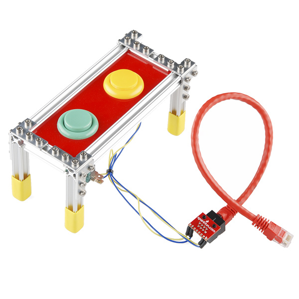
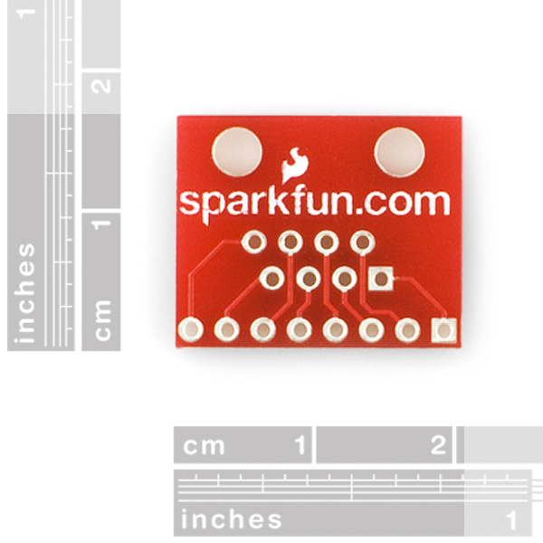
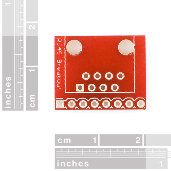
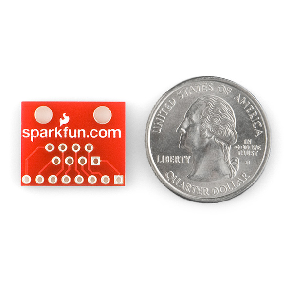
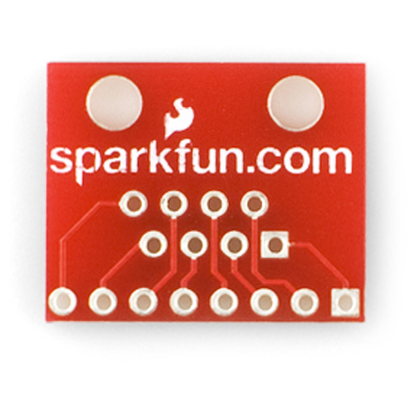
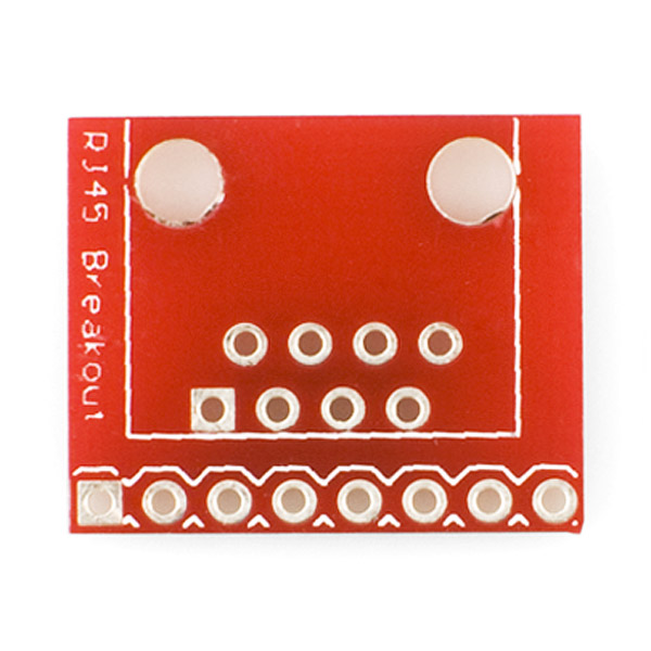
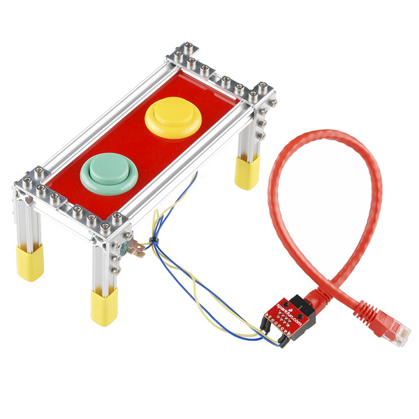
These are a really nice way to break out an RJ45 plug to 0.1" headers. Our FIRST Robotics team replaced most of our servo PWM cables with Cat 5 using these.
Only comment: It would be nice it the board had two more holes in it so you could easily fasten it down to another surface.
I just noticed that there is no way to attach these. What a shame that they don't have screw holes.
FWIW, these breakout boards work perfectly with these very cost-effective RJ45 jacks from Jameco: https://www.jameco.com/webapp/wcs/stores/servlet/ProductDisplay?langId=-1&storeId=10001&productId=1537416&catalogId=10001&krypto=9x3mj8umRTpEiUpc4g3o46VWVeKoQOF4W0KGbu6hapIWj2QpMUWcjg%3D%3D&ddkey=https:StoreCatalogDrillDownView
I bought this along with the PRT-00643 connector and it seems that the breakout is 180 degrees out from the connector.... that is if pin 1 is the square pin. Or do I need to go back to school and learn my numbers and shapes?
As noted by others, the pin numbers are backwards if you assume that pin 1 is the square pin. This is related to the RJ45 jack that is used. If you use the SparkFun PRT-00643 which has the locking tab at the bottom, the pins will be reversed (the square pin is pin 8). If you use a jack with the locking tab at the top the pin numbers will be correct.
Will this Molex Jumber 2 Wire assembly fit with an rj-45 on this board? PRT-09918 https://www.sparkfun.com/products/9918
Works fine except the pin 1 designation (the square-shaped pad) is wrong, as noted by another commenter. The pins are in reverse: i.e. the pin 1 designation is actually designating pin 8.
Anyone know the maximum continuous current that the traces on this board can handle? In other words, are the traces >= 24 gauge wire?
It seems that the "Pin 1" indication (square pad) on this breakout is wrong, at least with the connector that you provide. I almost fried something in a PoE-setup :)
So how have people attached these to their projects?
What is pin 1?
Very nice! Easy assembly. Comes in handy for working with RJ45 for non Ethernet uses.
Very handy! I have older versions of these that work great.
This works great with both the Sparkfun MagJack and Pulse Magnetics J00-00XXNL parts.
Wish that board included the LED pins, with grounds routed together and 0805 resistor footprints on the board. That would make this a plug-in solution, as it stands I have to route this stuff myself. Kinda a hassle.
I use them (with the RJ45 8-Pin Connector) more and more to connect two bread boards over some distance and it works great. I just wished there would be mounting holes, because the cable can pull quite a bit...
breakboarding?
Do you mean "breadboarding"? If not, what is breakboarding?
Use this one: http://www.sparkfun.com/products/8790