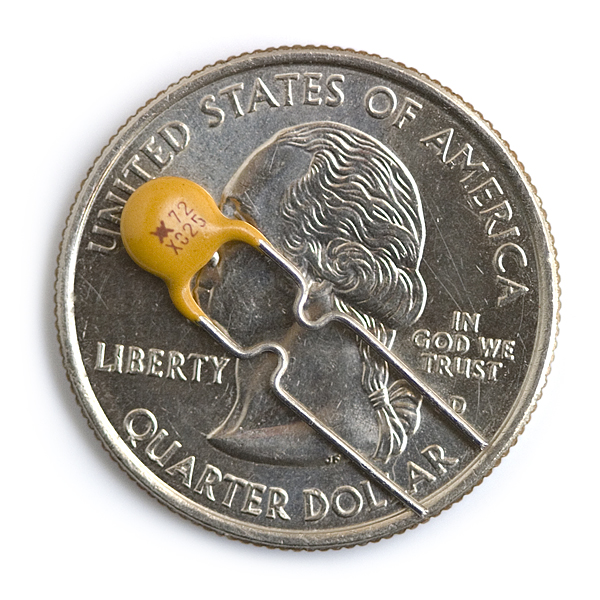
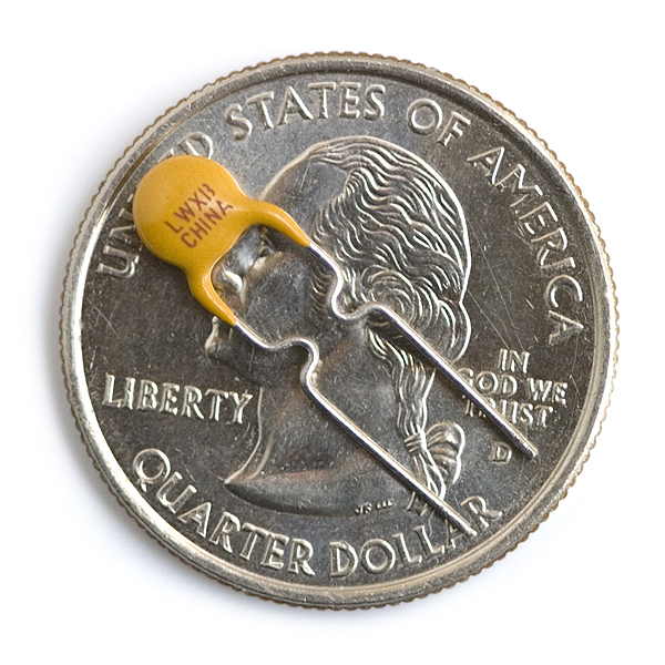
This is a handy little device that can save your system from smoking. A resettable fuse (also known as a PTC) is a resistor that has very unique properties.
For this model, if your circuit tries to draw more than 250mA of current (if you have a bad short for instance) the PTC would 'trip' (by heating up). The increased resistance (trip state) would break the circuit and allow only a small leakage current.
The leakage current may still be enough to hurt some electronics but it's much less than the 3A that the short may have allowed. Removing the short, the PTC 'resets' and allows current up to 250mA to flow again. It's a resettable fuse that protects your system! Good for use on battery powered devices that need to protect again high-current accidental discharges.
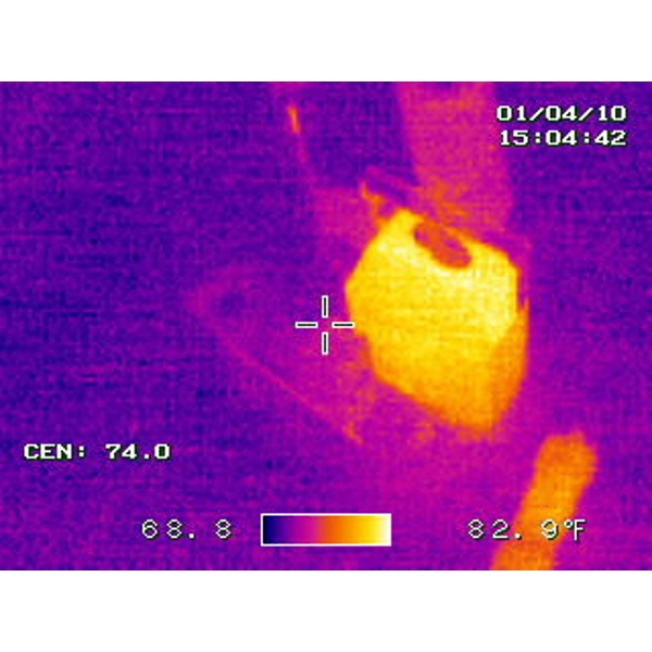
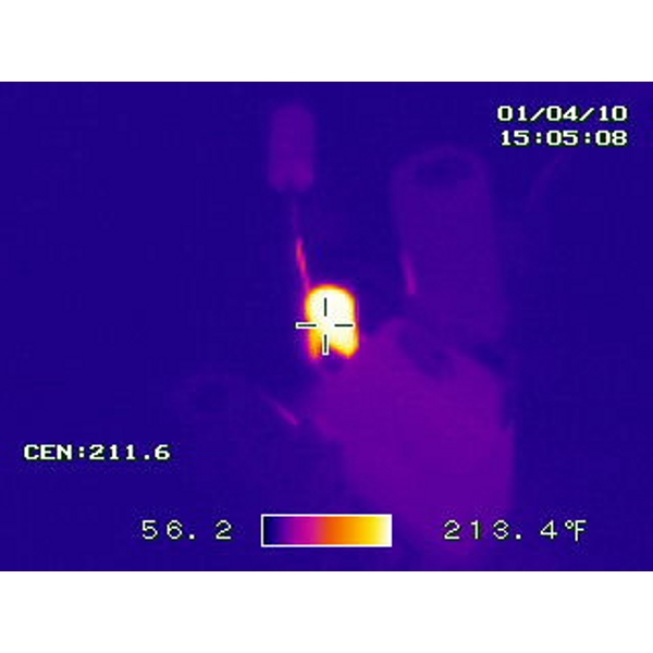
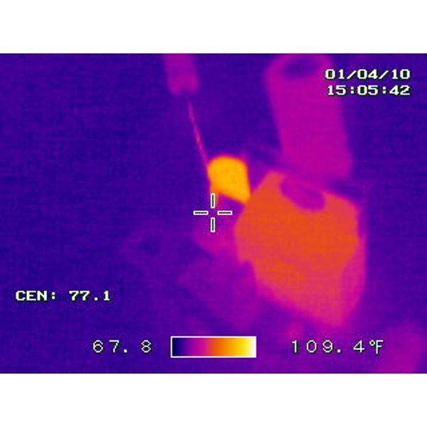
The thermal pictures to the right do a great job of showing what happens when the PTC is tripped. The first thermal picture shows a voltage regulating circuit in its normal state. In the second picture the circuit is shorted, notice how hot the PTC gets (213 °F!) as it limits the amount of damaging current going through the circuit. Major thanks to Joshua Weaver for the great thermal shots!
Resettable Fuse PTC Product Help and Resources
Fuse Breakout Board Hookup Guide
October 3, 2019
Protect your project by adding a fuse in your circuit to save it from molten destruction.
Core Skill: Soldering
This skill defines how difficult the soldering is on a particular product. It might be a couple simple solder joints, or require special reflow tools.
Skill Level: Noob - Some basic soldering is required, but it is limited to a just a few pins, basic through-hole soldering, and couple (if any) polarized components. A basic soldering iron is all you should need.
See all skill levels
Core Skill: Electrical Prototyping
If it requires power, you need to know how much, what all the pins do, and how to hook it up. You may need to reference datasheets, schematics, and know the ins and outs of electronics.
Skill Level: Noob - You don't need to reference a datasheet, but you will need to know basic power requirements.
See all skill levels
Comments
Looking for answers to technical questions?
We welcome your comments and suggestions below. However, if you are looking for solutions to technical questions please see our Technical Assistance page.
Customer Reviews
No reviews yet.

Could a tantalum capacitor also kinda work? It would smoke, making a very visible change
Typo: You said again instead of against
Couldn't these be used as temperature sensors?
Interesting idea! You could series it with another resistor, add a voltage source then read the divided voltage, you need to make sure that the other resistor's resistance does not change.
[+5vdc]-----/\/\/\/\/----*---|PTC|-----------[GND]
I think a good value for R is the max value of Rptc
A PTC is a non-linear thermistor, so it can, but its not great at it.
So what is Imax? I see this spec in some PTC devices as high as: Maximum Electrical Rating Voltage: 30Vdc MAX Current: 100A MAX
What does this mean?
You guys really should sell SMD PTCs, I assume you have a lot of them anyway.
I noticed this type of fuse has 2 amp ratings, "hold" and "trip". Which one is used to determine when the fuse stops/reduces current?? I would assume the "trip" one would be the right one but after some goggling I'm not so sure. This is how I understand the 2 ratings, correct me if i'm wrong,the "hold" rating is when the fuse starts to increase resistance and the "trip" is when it has completely stopped.
So say I want to protect a 2A circuit which rating should i go by??
If it's normally drawing 2A, you'd want one that has a hold of 2A or even a little bit above. The region between hold and trip is basically an unknown state in which it may proceed to trip, or it may be fine. The trip current is where they know with high certainty, for a given ambient temperature (check the datasheet of the devices you'd be looking at!) that the package will not be able to dissipate the heat generated quickly enough and thus cause an escalation of the resistance.
One thing you may want to keep in mind as well is what you're trying to protect your circuit from, and how critically so. Scouring Digikey for a component, Ihold at 2A gives me a minimum Itrip of 3.5A - but at that 3.5A, it'll take quite a while for it to actually reach that trip 'point' (checked 2 manufacturers). You can see that in the datasheet for this fuse as well - "Time to trip" is stated as a maximum of 2.5 seconds at 1.25A in 20°C.. but if you look to the left, the 'trip current' at 20°C is said to be 0.5A - so it'll take a fair bit longer. If that's not acceptable for your use case, you may have to check alternatives.
OK thanks, basically I want to protect against short circuits in a power supply.
In that case, you may additionally wish to add a regular fuse to cut all power if the PPTC fails to trip adequately (if leakage current is an issue, for example). At least a short circuit should make sure the current is high enough that it would react fairly quickly :)
Shall we use the 16V, 15A PTC Fuse in the 250VAC. Kindly confirm the same.
So, this isn't the same PTC that's used on the USB breadboard power supply? 'cause that one says 500ma protection. Where do I find the 500ma version?
Is there any 30 amp resettable fuse?
Just put 120 of them in parallel :)
http://www.mouser.com/ProductDetail/TE-Connectivity/MHP30-36-T/?qs=HSSPLe7ToFFbhY9dFfZLyw%3d%3d
Not here.
Looks like a better method than watching for blue smoke. Now, if only I could find some temperature-sensitive ink to dip these in so I could see what it's doing... I wouldn't want to touch the one in the fourth picture.
Can you get the 500mA version also please.
Put two in parallel.
So... Putting two in parallel will make them trip at 500mA?
Not that I don't believe you, but just to make sure, can anyone else verify this?
I believe so. If they are connected at the same points, since they have the same resistance, current should flow equally through them. At 500mA, 250mA will flow through each one. I think.
Normally the assumption that they're the same resistance would be a bad idea as this is almost never the case. However, this system is likely self stabilizing, since a mismatch in the current is likely to bring rise to a mismatch in heating, and subsequently keep the two approximately in balance. Nevertheless, I don't think it'd be safe to say that two in parallel will work without doing a sensitivity analysis on both variations in the resistance and variations in the thermal coefficient; there may be unstable combinations, or combinations that are stable with a cutoff point significantly less than 500mA.
An NTC (negative temperature coefficient) would be nice... if they existed.
Okay, seriously this time. How quickly do these cool down and reset?
An NTC would not do the same job. It would let high currents through, but not small ones.
Basically, a PTC designed for current limiting has a resistance in the range of a few ohms to a few hundred milliohms at normal temperatures. Current through this resistance dissipates power, causing a rise in temperature, which in turn increases the resistance and the power dissipation. This increased resistance drops the output voltage. Under normal operation, this is checked by the dissipation of the case (seen in the thermal images), but under higher currents, thermal runaway occurs.
The Epcos datasheets do a much better job of describing their operation than this one does. See http://www.epcos.com/inf/55/db/PTC_09/OC_Leaded_12V_160_C2_B0C_C_B599_5.pdf , and look at the graph "Switching time tS versus switching current IS". You'll see that, for the Epcos PTCs, they take (very) roughly 1 second to turn off at their rated current, 10s at half that, and will conduct double that for 100ms. This is good for some applications (motor drivers, heater elments, etc.) but not for others (microcontrollers, digital logic).
If you want something that will get cold when you pass current through it, look for Peltier cells.
Right, they don't do the same job. They can be useful, however. Putting one in a power supply lets it "soft start", avoiding straining the rectifiers on powerup, trying to dump current into a discharged filter capacitor too fast. It starts off at a high resistance, limiting charge current, then as it warms up, lets more current flow.
Alright so NTC's do exist - just found that out. Wish I could quit impulse posting lol...