FM Radio Transmitter Breakout- NS73M
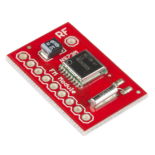
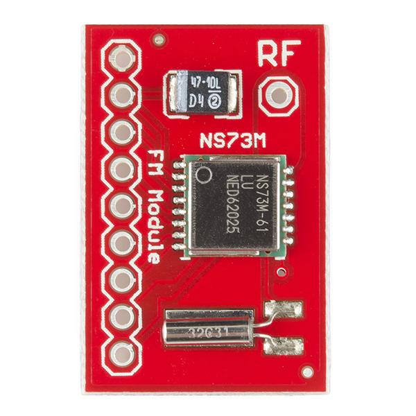
Enable your next embedded project with FM broadcast ability. This small module packs some power. With a 2mW maximum broadcast power we've been able to transmit up to 60ft with a simple 31" piece of wire (1/4 wave of 95MHz). Built upon the NS73M module, it is digitally tune-able from 87MHz up to 108MHz. Right and left channels are available for stereo broadcast as well!
This product is meant for research purposes and is not FCC certified. The NS73M part is not certified by itself (certification requires an antenna be attached) but has been used and certified in many consumer products.
Note: An antenna is required. We've used a 31" piece of 22 gauge basic hook up wire with great results.
- 87.5MHz to 108MHz
- Stereo multiplexing modulation
- Simple external 32.768kHz
- Small size
- Alignment free
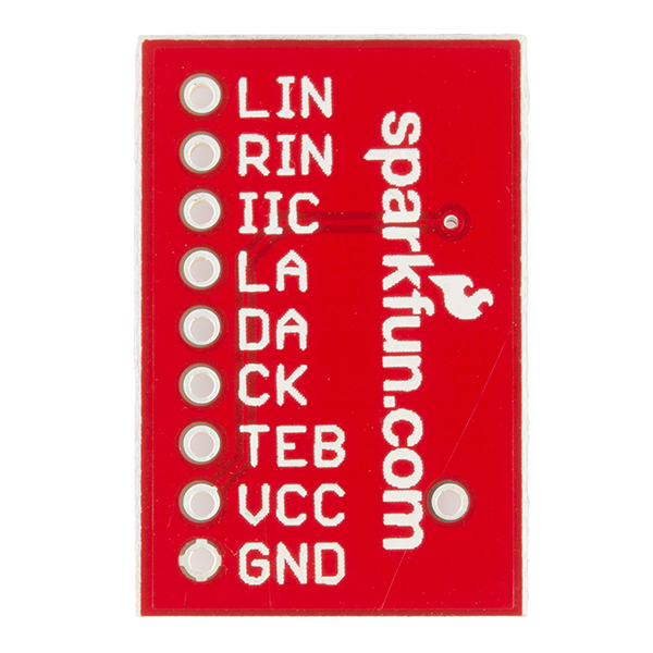
- SPI and I2C supported interfaces
- 2.7V to 3.6V
- -20C to 75C operation
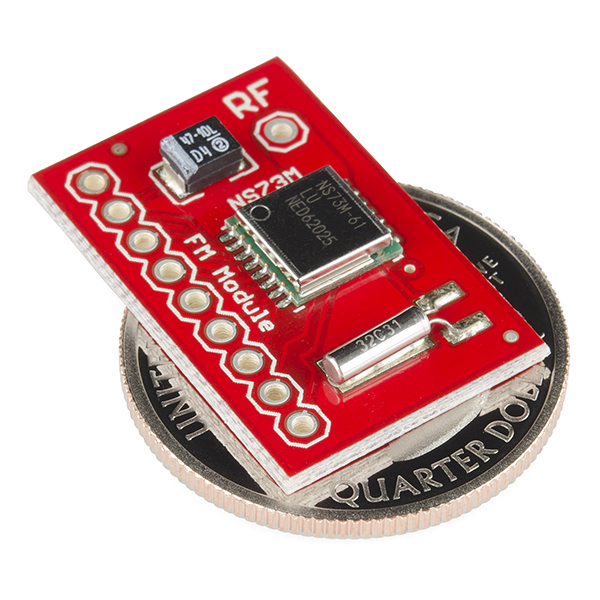
1.0x0.65"
Documents:
- NS73M Description
- NS73M Datasheet
- Example 3-wire control
- Example code in Basic
FM Radio Transmitter Breakout- NS73M Product Help and Resources
Core Skill: Soldering
This skill defines how difficult the soldering is on a particular product. It might be a couple simple solder joints, or require special reflow tools.
Skill Level: Noob - Some basic soldering is required, but it is limited to a just a few pins, basic through-hole soldering, and couple (if any) polarized components. A basic soldering iron is all you should need.
See all skill levels
Core Skill: Electrical Prototyping
If it requires power, you need to know how much, what all the pins do, and how to hook it up. You may need to reference datasheets, schematics, and know the ins and outs of electronics.
Skill Level: Rookie - You may be required to know a bit more about the component, such as orientation, or how to hook it up, in addition to power requirements. You will need to understand polarized components.
See all skill levels
Comments
Looking for answers to technical questions?
We welcome your comments and suggestions below. However, if you are looking for solutions to technical questions please see our Technical Assistance page.
Customer Reviews
No reviews yet.


is it possible to get the Gerber files for this breakout board?
While it looks like the Eagle files on this may have been lost, we do have the gerbers for the panel to order PCBs on file. Please contact support@sparkfun.com and they should be able to get those to you.
see this link on OSHPark https://oshpark.com/shared_projects/KQqQboMv
Hi – I bought an FM transmitter from SparkFun (product URL at bottom). In fact, I bought ~8 of these so far. Ive been unable to affix leads to each of the contacts. Any help is appreciated before I buy 80x more!
https://www.sparkfun.com/products/8452
Do I even need to solder leads to all 8+7 (15) contacts!?
Please consider changing the name of this item so that it is more clear that this is a TRANSMITTER and not another receiver.
I agree with Rcrowley. I didn't realize this was a transmitter until I read this comment.
Thanks.
The description says that this module is a transmitter.
I've realized a small ATtiny85 development, you can find here the electronic scheme: http://www.paratte.ch/Jean-Marc/tiny85_variometer/tiny85_variometer_develop_1.pdf
It's a variometer/altimeter built with a BMP085 Breakout and audio bips are sent via a NS73M Breakout.
All ICs/Breakouts are linked via I2C. Note that the BMP085 Breakout includes 4k7 pull-up on SCL & SDA lines.
This circuit works well but with 2 observations:
1/ SCL line must have a fast rise-up time else the NS73M can't initialize. I've observed that my development ISP cable & custom electronics are too capacitive. I've added another 1k5 pull-up on SCL line to solve the problem.
2/ Because it's a variometer, the BMP085 is permanently asked via I2C bus. And we heard I2C pulses on FM as a light white sound. I think I need to disconnect the NS73M from the I2C bus after initialization to clear the sound.
Hi! Did you manage to solve the problem with the noise from the I2C bus? I'm interested to hear about your solution.
It would be great to have a board based on the Si4713 which provides RDS encoding as well. That is what i am looking for.
I am having a strange problem with the NS73M board: I run it with an Arduino via I2C. The I2C lines are pulled up to 3.3V via 10k resistors. Everything works great. I can adjust the transmit frequency, adjust the output power etc...However, when I connect an audio source (~100mV) to one of the inputs the I2C communication dies. Sometimes it keeps working for a few commands, usually it is dead right away. When I connect the audio source the audio is transmitted, i.e. this works. But somehow it is influencing the I2C setup. I tried several audio sources including a AD9833 waveform generator chip...always the same. After I2C dies, I have to power down everything for a few minutes. Then I can communicate again...I tried this with two different NS73 boards, i.e. the boards are probably not the problem...Any input will be appreciated! Thanks!
I am having the same issue. I2C works fine up until when you add audio. I think once audio is added it locks the IC from I2C to maintain the broadcast channel. My only guess would be to power cycle the NS73M once a new channel is selected using a 2n4401 and a little code after the ON AIR command is given. Or you could just use a switch.
It would be very useful to have a Quickstart Guide for this product, similar to the one you have for the Si4703 Tuner.
I'll get a bug submitted to get one written up. This a slower seller though and will be lower on the priority list, so it may be a while.
For anyone considering this part: It truly is a great FM transmitter! I've made something similar to http://www.km5z.us/FM-Stereo-Broadcaster.php However I notice that some noise of the electronics is picked up in the signal. As I'm not really an expert in this, can anyone give me advise on how I can make sure this doesn't happen? Probably a capacitor somewhere (where??) or shielding of the audio lines? Many thanks!
Try reducing the charge pump value. Check out the datasheet for the SPI codes to send the chip. I was frustrated with this too, and when I changed the charge pump value, it started working very nicely.
Thx for the advice, but unfortunately didn't help. I set register 0x06 to value b00011010 instead of b00011110. Also, I'm using I2C communication, don't know if this matters... Next to changing the charge pump value, I also completely rewired, resoldered all parts to no purpose :-( Any other ideas? Could it be the antenna? I now soldered about 80cm of stranded hookup wire onto the breakout board.
If you're broadcasting in mono turn of the pilot tone and the sub-carrier and enjoy the silence. In other words, set register R01 to:
b11111100
FM stereo is a kludge. Don't use it if you don't have to.
Anyone interested in the part should try running a half-wave dipole. Monopole is going to be lousy with only a tiny ground plane.
It's an analog transmitter... to use with an embedded digital device it must have a DAC, or at least a tone generator of some kind. The simplest thing you could do on Arduino or similar board is to implement morse code that can be received on FM radio. Use a square wave near 500 Hz. That's a pretty lame application, but analog systems tend to require more analog or relatively sophisticated digital. It would be easier to hook the damn thing directly to a turntable, for example, than it is to get a cool app out of an Arduino.
I had one of these running for about 6 months in a circuit that I prototyped so I could have music in my car. It wasn't the best, but it was good enough for my uses. After about 6 months or so, the transmitter mysteriously died. Everything seems to be operational with everything else, but it just doesn't broadcast anymore.
Any ideas of what could have went wrong? I had it turned on going down the road and suddenly it just turned off. When I got where I was going, I checked it and there was nothing loose or that could've shorted it in anyway. I had a small capacitor over the power lines as well to try to absorb noise. The power basically went USB car adapter -> Arduino -> FM transmitter.
I tried to use this board with Breakout Board for ADMP401 MEMS Microphone (http://www.sparkfun.com/products/9868) to create mini radio station but I cannot get a FM radio to receive any audio out of it. Please help!
I found the solution at:
http://www.km5z.us/FM-Stereo-Broadcaster.php
Can the transmission span be changed to the woldwide FM band
76 - 108 Mhz by using a different crystal? Or maybe lowered a
bit below 88 Mhz. Any vendors for such a crystal? Thanks!
Does anyone know how/if this would work with an Arduino? If so, does anyone have example code?
I don't have any code to actually do this, but it should be possible to use this board with an Arduino. Since most Arduinos can output 3.3V for power and all can interface either using SPI, I2C.
hi
previous comment link is change to link.
One more info is that Niigata create a new chip that is NS741 and that support RDS. Unfortunatly that company's website is not so usefull to retrieve needed info.
One more... I'm developing board to directly interface NS73 with ATtiny45 that use VUSB library to directly connect to PC...more info should be provided in next week.
Just got this it is a great little board, easy to solder headers to, and small. But the board is red not green.
As a newbie, I hope someone can help me with my possibly "dumb" question. wht exactly do I need to do to get this one working? aside from an antenna that is? for instance the digital tuning part? how exactly? <br />
thanks!
I'm poking a necro post I know, but in answer to your question, for others... this guy wrote a really nice blog piece on the part:
http://iamgew.com/2013/05/07/fm-transmitter/
Someone from Sparkfun send him a gift certificate (and a scolding for not posting it here himself). Very nice, and way cheaper than hacking the buttons on a C Crane FM xmitter.
Be sure to check the GitHub code from the above link, as part of the code to change the station was omitted from the page.
Here's the GitHub link from the above page. https://github.com/gohengwei/FMTransmitter
Read the documents theres a lot of very helpfull information in there.