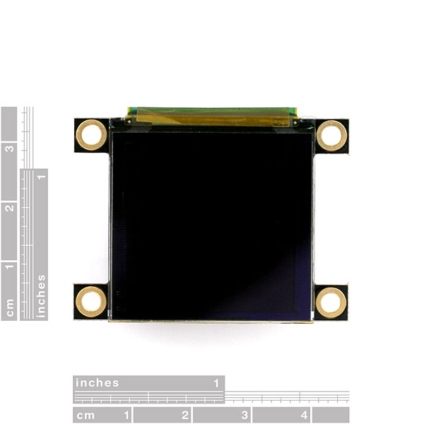
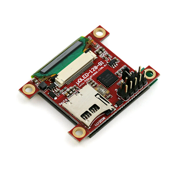
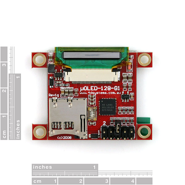
Serial Miniature OLED Module - 1.5" (uOLED-128-G1GFX)
Replacement:LCD-11676. This OLED has been replaced with the G2 version which has some minor hardware and software updates.
4D Systems' line of smart miniature OLEDs make it easy to add dazzling, full-color graphics and text to your embedded project. By incorporating their powerful GOLDELOX embedded graphics controller, 4D has taken the load off of your system. The uOLED board also has an on-board uSD card slot where you can store images, animations, icons, etc.
Two different firmwares are available from 4D Systems and either of the two can be loaded onto the GOLDELOX chip at any time. The GFX firmware is designed to act as a standalone microcontroller which you can program with the 4DGL language, which is similar to C. The SGC firmware configures the module to act as a slave processor, communicated via serial and handling only the graphics processing tasks while your favorite microcontroller does the external control.
The uOLED-128-G1 is a "middle-sized" smart miniature OLEDs from 4D Systems measuring in with a 1.5" screen. Check out the 4D Systems product page for more information about the firmware options (PmmC) and how to swap them out!
Note: It's been brought to our attention that trying to program the 4D screens using an FTDI breakout can damage the driver. You'll need to use the FT232RQ USB to Serial which you can find in the related items below.
- 128x128 pixel resolution
- 65K true to life colors
- 1.5" diagonal display
- OLED requires no backlight with near 180 degree viewing angle
- Easy 5 pin interface to any host device: VCC, TX, RX, GND, RESET
- Voltage supply from 3.6V to 6.0V @ 40mA nominal when using a 5.0V supply
- Serial TTL (0V to 3.3V) with auto-baud feature (300 to 256Kbps). If interfacing to a system greater than 3.6V supply, a series resistor (1K) is required on the RX line.
- Powered by the 4D-Labs GOLDELOX-GFX2 graphics processor highly optimized for 4DGL, the high level 4D Graphics Language.
- Onboard micro-SD (uSD) memory card socket for storing of icons, images, animations, etc. (64Mb to 2Gb)
- Three selectable font sizes (5x7, 8x8 and 8x12)
- Built in graphics commands: LINE, CIRCLE, RECTANGLE, TEXT, USER BITMAP, BACKGROUND COLOUR, PUT PIXEL, IMAGE, etc.
- 45.5x33.5x8.8mm
Comments
Looking for answers to technical questions?
We welcome your comments and suggestions below. However, if you are looking for solutions to technical questions please see our Technical Assistance page.
Customer Reviews
No reviews yet.


just saw one of these on eBay, put a bid in so far im winning at $0.99. if anyone wants to go against me here's the link http://cgi.ebay.com/ws/eBayISAPI.dll?ViewItem&item=280513717483&ssPageName=STRK
Hi all, I recently purchase one of these but am having problems. I believe I have the GFX version, when I turn it on, there is a graphics clock face with a green background. I want to load the SCG firmware so I downloaded the PmmCLoader and the appropriate SCG firmware. I am using an older Sparkfun Breakout board based on the FT232 similar to the BOB 00718 with DRT connected to reset and RX and TX crossed between the two boards. The 4D is running from 5v. The PmmCLoader says "Waiting for device" and stops. The graphics clock animation stops but it appears that the serial port is not communicating. When I cancel the load, the display resets. 4D makes a big deal out of using their USB to serial boards but its not clear how they are different. If have also used another serial board based on the Silabs chip with same result. Anyone have any ideas on what is wrong? The real 4D USB to Serial boards are out of stock.
I got one a couple weeks ago with the same result. I tried to load the correct firmware using a cheap usb to rs-232 with no success. Sparkfun technicians are aware of this as well, and are working on flashing all of their stock LCD's that have the incorrect firmware. If you got one with the wrong firmware recently, chances are they'll re-program it for you. These LCD's are very easy to work with and display vivid color with no noticable data noise on the pixels. Great product!
Ive got the uOLED 128 sgc and cant get it to do anything with the uSD card. Anyone have any luck with this or the 4D systems simulators?
Could I possibly just run my own 3.3V into the 3.3VOUT pin on the display to power it? Has anyone tried this and if, successfully?
This is a beautiful display and beats the backlit Nokia type LCDs any day. Just a bit on the expensive side.
If anyone has had success uploading an image to the SD card and viewing it using arduino code then please let me know. I've loaded images using Graphics composer to the correct sector and tried with no luck displaying them.
After agonizing over the 0.96" screen with nearly the same controller for months and going through all the outdated or dysfunctional libraries available for it, I found one that works with the Uno / 328 and the most recent Arduino IDE. Again, this is all for a slightly different screen, but it is a decent hello world for 4D serial controlled screens.
The library is available at: http://code.google.com/p/arduino-oled/
And I wrote up a basic Oscilloscope sketch for it that includes a trigger feature, it's posted at:
http://nodechomsky.com/post/3749787199/oscilloscope-for-arduino-and-4d-graphics-controller
and video of it in action (it's a bit blurry, but my camera is awful)
http://nodechomsky.com/post/3750164143/this-is-the-output-from-my-arduino-based-diy
Hi all,
Just got mine yesterday. I want to display value from a BasicAtom Pro 28.
I am lost and don't know how to do.
Any help ?
The library jenny has doesn't work anymore due to ArduinoIDE losing the printbyte command, you'll have to slightly modify the commands. use BYTE ex> (0x73, BYTE). This works fine for me. Also be careful on powering it. It can draw up to 140ma if the screen is full white (basically all LEDS on)
I'm sooo lost! I'm trying to display images using an arduino. I followed Jenny's tutorial but I used the new library. I tried to swap out her printByte commands with the sdWriteByte command in the new library but it doesn't work! I also tried to use the displayImage command but with no luck either. Has anyone had any luck with this?
-Slaps
I have been through the exact same thing, I am still no closer to figuring out how to make use of this thing. I wish I could I have a lot of uses for it, but I have yet to find any way to make this thing interact with my arduino.
The display will work with the 3.7v Li-Po batteries, see this instruction for a watch made with the display. http://www.instructables.com/id/Arduino-Watch-Build-Instructions/
Also the Tutorial by Jenny is out of date, the current library that works with Arduino's can be found here. http://code.google.com/p/uoled-library/
Your watch inspired me so much I have decided to totally redesign my project (not exactly a watch) for Instructables' USB contest. This screen looks like an awesome piece of kit!
Thanks for the link! I'll really need it during the next 2 weeks.
It also says "Voltage supply from 3.6V to 6.0V @ 40mA nominal when using a 5.0V supply".
The SD or 3.3v output at maximum current when working might need 5v to avoid dropouts, but I suspect if you don't use the SD or 3.3 out (or not too many mA) it would work at 3.6v LiPo just fine.
The one I got worked fine from 3.3v from the FTDI breakout.
YMMV, but I was pleasantly surprised, though I ordered two different 3.x-5v up-converters to try since I thought I would need them.
Can these be powered and be fully functional using a 3v3 Li-Po battery?
The datasheet states that for sd functionality you need 5v, but I don t see why is that. SDs work at 3v3.